background image

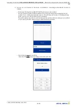
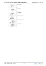
Set a new PIN to prevent unauthorised access.

9. If required, enter a name of your choice (alias)

Example: 01_ECblue

Assembly instructions 

ECblue BASIC-MODBUS, ECblue BASIC

Bluetooth communication module AM-STICK-

WB

L-BAL-F079D-GB 2044 Index 002

Part.-No. 

46/80

Содержание ECblue BASIC-MODBUS

Страница 1: ...e BASIC MODBUS ECblue BASIC Motor sizes D 116 G 152 EC fans and motors with and highest ef ciency for livestock houses Assembly instructions Keep for reference L BAL F079D GB 2044 Index 002 Part No en...

Страница 2: ...onal description 12 3 3 Name plate 12 3 4 Temperature management 14 3 5 Note on the ErP directive 14 3 6 Transport storage 14 3 7 Disposal recycling 14 4 Mounting 15 4 1 General notes 15 4 2 Connectio...

Страница 3: ...ons 37 5 17 Accesories main swithc Zenec 37 5 18 add on modules for ECblue BASIC 38 6 Start up 39 6 1 Prerequisites for commissioning 39 7 Communication options for programming 40 8 Bluetooth communic...

Страница 4: ...0 12 2 1 UL Ratings 70 12 2 2 UL Overload protection 71 12 2 3 UL Short Circuit Current Rating 72 12 3 Connection diagrams 73 12 4 Application examples 75 12 4 1 Installation with ventilation computer...

Страница 5: ...tain safety instruc tions that must be complied with as well as information that is required for failure free operation of the device Keep these assembly instructions together with the device It must...

Страница 6: ...refore not taken into consideration in translations 1 7 1 FCC IC Statements AM MODBUS W AM PREMIUM W In case that the AM MODBUS W module or the AM PREMIUM W module is installed in the ECblue the follo...

Страница 7: ...ennas which are listed below complies with Part 15 of the FCC Rules The device meets the requirements for modular transmitter approval as detailed in FCC public Notice DA00 1407 transmitter Operation...

Страница 8: ...is licensed to meet the regulatory requirements of Industry Canada IC license IC 216Q 1740 Manufacturers of mobile xed or portable devices incorporating this module are advised to clarify any regulat...

Страница 9: ...es obligations incluent une tiquette clairement visible l ext rieur de l embal lage externe comportant l identi ant IC du module Panasonic inclus ainsi que la noti cation ci dessus Les identi ants IC...

Страница 10: ...ed to be reliable The device and its accessories must only be used in a awless condition and installed and operated in compliance with the assembly instructions and or operating instructions Operating...

Страница 11: ...personnel Waiting period at least 3 minutes Through use of capacitors danger of death exists even after switching off the device through directly touching the energized parts or due to parts that hav...

Страница 12: ...line with their intended use The supplied and certi ed guard grille of ZIEHL ABEGG SE fans is designed in accordance with DIN EN ISO 13857 Table 4 from the age of 14 up In the event of deviations fur...

Страница 13: ...nufacture 18 Protection rating Max ambient temperature authorisation at rated power 6 Partnumber ZIEHL ABEGG SE 19 Current output in case of short circuit 7 Series number 20 Indication of more detaile...

Страница 14: ...ee rating plate and the permissible carrying loads of the means of transport Wear safety clothing shoes and cut resistant safety gloves when handling Transport the fan s either in the original packagi...

Страница 15: ...o EN 60335 If the mounting height danger area above the reference plane is greater than or equal to 2700 mm and is not reduced by auxiliary means such as chairs ladders working platforms or oor space...

Страница 16: ...at 80 100 of maximum speed to remove any moisture that has penetrated inside 4 5 Motorheating A continuous power supply is required for safe operation down to the minimum permitted ambient temperatur...

Страница 17: ...ealing the conduit connections make sure the supplied O rings are used When screwing the conduits into the thread adapters use UL approved sealing tape e g Te on tape The opposite end of the installat...

Страница 18: ...70 friction coefcient ges 0 12 7 Nm 17 Nm 33 Nm Screw penetration 1 5 x d 1 5 x d 1 5 x d When using screws with different friction values or strength classes different tightening torques may be nece...

Страница 19: ...wall and tighten with cable tie 5 to fan support arm 4 8 2 Mounting with stainless steel brackets Mounting the stainless steel brackets is done with a separately obtainable installation kit gure 1 Mar...

Страница 20: ...N ISO 10 511 self locking 4 10a 8 4 washer EN ISO 7089 4 All fastening elements made of stainless steel 4 9 ZAplus fans When mounting ZAplus fans ensure plastic compliant connectors Recommended tighte...

Страница 21: ...fcient ges 0 12 9 5 Nm 23 Nm Screw penetration 0 83 x d 0 83 x d Max permissible screw overhang 1 0 mm 1 5 mm 5 Electrical installation 5 1 Safety precautions Danger due to electric current Work on el...

Страница 22: ...lue BASIC connection version example 1 ECblue for line and relay hose cable 5 x 1 5 mm2 LiF9Y11Y JB BN BU GNYE WH WH brown L1 Voltage supply blue N green yellow PE white 11 Relay white 14 K1 3 ECblue...

Страница 23: ...condition at delivery Remove plastic fastener if necessary and insert enclosed cable glands entry points that are not used must remain sealed 3 Insert and connect lines correctly note the respective...

Страница 24: ...Conductor cross section rigid min 0 2 mm2 0 2 mm2 0 2 mm2 Conductor cross section rigid max 10 mm2 1 5 mm2 1 5 mm2 Conductor cross section exible min 0 2 mm2 0 25 mm2 0 2 mm2 Conductor cross section e...

Страница 25: ...ten the collar to the speci ed torque with a suitable torque wrench Insert the cable through the cable gland into the housing Fit the union nut by hand and tighten slightly Tighten the union nut to th...

Страница 26: ...ation grease dust or other impurities Use of a damaged cable is not allowed Two lines may only be fed through one cable gland with a sealing insert for two lines When using the seal insert for two cab...

Страница 27: ...tegration into different networks X With AM MODBUS auxiliary module possible 5 5 EMC compatible installation 5 5 1 Harmonics current for 3 types According to EN 61000 3 2 these devices are to be class...

Страница 28: ...cable the type of routing the operating conditions and according to the standards applicable on site The speci cation for the maximum admissible line fuse of the device must be observed see technical...

Страница 29: ...mains connection and the PE conductor and they are therefore suitable for use in a Grounded Delta System 5 7 Systems with residual current protective devices Whether the use of a residual current pro...

Страница 30: ...on 10V GND E1 10 k Speed setting by 10 k potentiometer at terminals 10 V and GND pick off at terminals E1 10V GND E1 24V PWM f 1 10 kHz 10 k 10 V GND E1 24 V E1 E1 GND 15 28 V Control via external set...

Страница 31: ...n external fault indicator is available over the potential free contact of the built in relay max contact rating see Technical data and connection diagram The relay is energised during operation I e o...

Страница 32: ...interface e g lightning Except the data link A D B D and GND for automatic addressing additional ID1 ID2 see following chapter no further cable cores of the data line may be used Pay attention to suf...

Страница 33: ...correct When using telephone cable with four cable cores we recommend the following allocation A D red B D black ID1 ID2 yellow for automatic addressing GND white Default interface parameter Baudrate...

Страница 34: ...the repeater of the Z G 1NE type can be used only it can relay the addressing signal Maximum number of members in automatic addressing With hand held terminal type A G 247 and control unit NETcon typ...

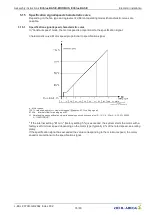
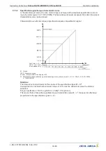
Страница 35: ...signal E1 Min Internal offset for analog input E1 Si Rotational speed speci cation signal depending on connection version 0 10 V 4 20 mA 0 100 PWM 0 100 MODBUS If the internal setting E1 min factory...

Страница 36: ...i Rotational speed speci cation signal depending on connection version 0 10 V 4 20 mA 0 100 PWM 0 100 MODBUS Relations The torque is set proportionally do the square of the speci cation signal M Si2 I...

Страница 37: ...an be made if required t a bridge between the GND terminal and the PE connection terminal for shield 5 17 Accesories main swithc Zenec Main switch for ECblue fans with 100 function Type Zenec Part No...

Страница 38: ...app AM PREMIUM AM PREMIUM W 349092 349051 Universal control module By plugging on the AM PREMIUM module the device becomes a universal controller sensors can be connected directly The device can be co...

Страница 39: ...y closed according to the suitable installation position 6 Connection data complies with the speci cations on the rating plate During start up check the following 1 Check the direction of rotation see...

Страница 40: ...the ZAset PC software Information For information on installation creating the connection and operation refer to the separate documentation for the auxiliary module Information on presets are not bin...

Страница 41: ...devices from version 11 onwards In a hard wired system wireless communication is primarily designed to provide a second interface for communicating with the device e g for con guration and diagnostic...

Страница 42: ...osition and make sure that clear assignment to the relevant product is possible This enables you to guarantee that even if the rating plate is covered up e g due to the installation situation easy com...

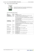
Страница 43: ...he Settings area with the gear wheel symbol 3 Switch on the line voltage to the fan frequency converter in compliance with the safety instruc tions 4 Activate the Bluetooth connection on the mobile de...

Страница 44: ...f necessary 6 ZAset then starts searching for devices in range and adds compatible devices to a list 7 Brie y tap the desired device in the list to select it ZAset Mobile then immediately establishes...

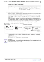
Страница 45: ...pens to link with the serial number If a binding already exists you have to enter the PIN see second stage The serial number can either be entered manually by reading it off and entering it in a text...

Страница 46: ...nauthorised access 9 If required enter a name of your choice alias Example 01_ECblue Assembly instructions ECblue BASIC MODBUS ECblue BASIC Bluetooth communication module AM STICK WB L BAL F079D GB 20...

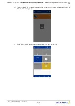
Страница 47: ...our of the Bluetooth symbol changes from red to green 11 Actual values on Dashboard when connection is established successfully Assembly instructions ECblue BASIC MODBUS ECblue BASIC Bluetooth communi...

Страница 48: ...ti cation etc 4 Error history 5 Parameter 6 back to Dashboard 7 Analysis 8 Speed control by variable Information Please observe the additional information in the app documentation and the operating in...

Страница 49: ...on in which operation at full speed is possible in case of failure of the setting signal It is selected by activating the setting Set Intern 2 factory setting 100 via the digital input When using the...

Страница 50: ...can be protected against unintentional changes by a pin code With further pin codes putting back to pre setting is possible PIN 0010 Release of the service settings with programmed PIN Accesslevel 0 s...

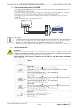
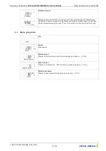
Страница 51: ...n the terminal with the P key 9 3 Menu group Info Info Speed Motor speed Motor current Display of internal motor current metering precision approx 10 Brake control Display of modulation 0 100 metering...

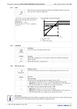
Страница 52: ...al3 via digital input possible see IO Setup 5 Fixed speed Default Internal2 without switching possibility to other default 6 Fixed speed Default Internal3 without switching possibility to other defaul...

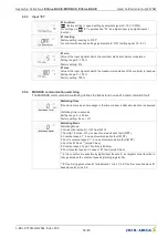
Страница 53: ...Accesslevel The PIN Accesslevel determines for which setting ranges a PIN must be entered Setting Function 2 Factory setting All menu groups are visible settings are possible without a PIN 1 The menu...

Страница 54: ...of ON required for 100 function If the analogue input E1 is not required for specifying the fan speed this can be used as a digital input see E1 function The same functions can be assigned for E1 as f...

Страница 55: ...is active at the digital input when the contact is open in factory setting D1 E1 Inverting OFF so that the maximum fan speed is still possible even when the line to the digital input is interrupted At...

Страница 56: ...ce receives no message in the time window a de nable function is executed Watchdog time in seconds Setting range 0 255 sec Factory setting 0 sec off Watchdog Mode Watchdog Mode 0 No function default O...

Страница 57: ...y setting 19200 UART Mode Setting transfer format Valid values 8N1 8O1 8E1 8N2 Factory setting 8E1 9 6 Menu group Motor Setup Motor Setup Rated speed MotorRatedCurr The following controller presetting...

Страница 58: ...Suppression2 Range2 min Range2 max Suppression3 Range3 max Range3 max Assembly instructions ECblue BASIC MODBUS ECblue BASIC Hand held terminal A G 247NW L BAL F079D GB 2044 Index 002 Part No 58 80...

Страница 59: ...0 3 4 1 2 09 05 2007 v_hochlaufzeit_ruecklaufzeit vsd 1 external Signal 2 Setting 3 Rampup time 4 Rampdown time 9 6 2 Suppression of speeds Suppression of up to three speed ranges Under certain circum...

Страница 60: ...device Diagnostic IGBT temp Display of the internal temperature of the power semiconductor Inside Temp Display of electronics internal temperature MCU Temp Display of the internal temperature of the...

Страница 61: ...he memory Example line fault Position 1 latest event The last 10 1 10 events are saved The desired position can be selected with the keys 19 number of all previous faults An error message appears alte...

Страница 62: ...shes When indicated clear foreign bodies dirt from the fan Active temperature management effective Motor or electronics overheated Check for free air passages remove foreign bodies if necessary see Im...

Страница 63: ...or mains phase the unit switches off after a delay approx 200 ms Only functioning with an adequate load for the controller Following a shutoff a startup attempt is made after approximately 15 seconds...

Страница 64: ...stay below the speci ed limit for more than 75 seconds the device will switch off with an error message 13 x 0 Line voltage too high Cause to high input voltage If the line voltage increases above a s...

Страница 65: ...ection at a setting signal above 0 To protect the electronics against too high braking current this function is partly fan dependent only possible up to a certain speed value The braking function also...

Страница 66: ...y impellers corroded in this way must be replaced immediately Deposits on the motor particularly on the cooling vanes and in recesses on the rotor can lead to reduced cooling performance and the motor...

Страница 67: ...e corresponding to the installation position must be checked for free passage In case of improper cleaning work no warranty is assumed regarding corrosion formation paint adhesion for unpainted painte...

Страница 68: ...mbient temperature valid for the respective fan Operation below 25 C as well as partial load operation for refrigeration applications is only possible with special bearings for refrigeration applicati...

Страница 69: ...monic current in accordance with EN 61000 3 2 are guaranteed For 3 types According to EN 61000 3 2 see Assembly instructions Electrical installation EMC compatible installation Harmonics current for 3...

Страница 70: ...0 W 16 kHz 7 4 A 218 Vac rms 70 MK 116 I 07 H MK 116 I 11 H MK 116 I H A16 MK116 0011 MK116 0019 3x 200 480 Vac 1300 2500W 4 0 3 2A 2400 W 16kHz 4 7 A 460Vac rms 40 3x 200 480 Vac 1180 2500W 3 2 3 6A...

Страница 71: ...2 0016 3x 200 480 Vac 3000 4100W 9 7 5 5A 2850 3900 W 16kHz 10 3 5 8 A 180 440Vac rms 50 3x 200 480 Vac 2600 4100W 8 6 5 6A 2470 3900 W 16kHz 9 5 8 A 180 440Vac rms 60 3x 200 480 Vac 1600 3000 W 6 0 4...

Страница 72: ...raz Shawmut TRS10R MK116 I I RK5 240 V 25 A 250 V e g Ferraz Shawmut TR25R MK116 I B MK116 I G MK152 I E RK5 240 V 50 A 250 V e g Ferraz Shawmut TR50R MK152 I B RK5 480 V 15 A 600 V e g Ferraz Shawmut...

Страница 73: ...485 PORT 1 PORT 2 Eingang Input 0 10 V 0 100 PWM 10 0 V 100 0 PWM 4 20 mA 4 0 100 1 Auto 0 100 3 01 1 Line voltage see rating plate 2 Relay output K1 for fault reporting factory function max contact l...

Страница 74: ...utput K1 for fault reporting factory function max contact load AC 250 V 2 A During operation the relay is energised i e the connections 13 and 14 are bridged In case of a fault the relay is de energis...

Страница 75: ...Cblue 5 Cable for line and relay at ECblue 6 conductor 5 not connected Danger due to electric current Make absolutely sure that the mains voltage and the control are a suf cient distance apart Assignm...

Страница 76: ...run between different buildings an effective excessive voltage protection is to be installed onsite on the rst device in the respective building Generally all surge arrestors work in such a way that...

Страница 77: ...hinery electrical equipment of machines Part 1 General requirements EN ISO 12100 2010 Safety of machinery General principles for design Risk assessment and risk reduction EN ISO 13857 2008 Safety of m...

Страница 78: ...ons of the EC Machinery Directive K nzelsau 28 10 2020 location date of issue ZIEHL ABEGG SE Dr W Angelis Head of Technics Ventilation Technology name function ZIEHL ABEGG SE Dr D Kappel Head of Elect...

Страница 79: ...e atmosphere 12 Imbalance 54 Input resistance 59 interface parameter 31 iPad 36 iPhone 36 IT System 27 L leakage current 60 lifting beam 14 line fuse 60 line protection 26 M MODBUS 30 MODBUS Recovery...

Страница 80: ...de http www ziehl abegg com 12 8 Service information If you have any technical questions while commissioning or regarding malfunctions please contact our technical support for control systems ventila...

Отзывы: