4.6.2
Connection in NFPA 79 Applications
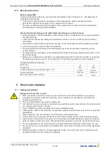
In applications where the NFPA 79 (Electrical Standard for industrial machinery) applies the
enclosed
cable glands can be used.
Attention!
•
Independent of the type and manner of the conduit / tube connection, correct connection of the
supply line(s), the safety of people and objects must be provided at all times.
•
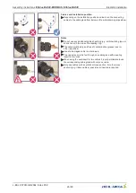
The locking screws used within the MK116 and MK152 series are only for shipment. For installation
the locking screws must be removed.
•
It must be used a connection technology suitable for the environmental type rating of the drive!
4.7
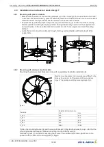
Fan designs A and D (without nozzles)
For attachment to
fi
xed motor
fl
ange use screws with property class A2-70 (stainless steel) to EN ISO
4014 and provide with suitable screw locking.
Permissible tightening torques M
A
Motor size
D
D
G
Thread size
M6
(Special application with 5-
pitch)
M8
M10
Stainless steel A2-70, friction coefcient
µ
ges = 0.12
7 Nm
17 Nm
33 Nm
Screw penetration
≥
1.5 x d
≥
1.5 x d
≥
1.5 x d
When using screws with different friction values or strength classes, different tightening torques may
be necessary.
Information
•
Pay attention to a suf
fi
cient screw-in length in the motor
fl
ange.
•
Excess screw length not permissible and it may result in the rotor being brushed against or blocked.
•
Every screwing case is different. The tightening torque adapted to it must be determined by the
appropriate screw tests.
•
Avoid structural damage or stress with installation. Make sure the surface is
fl
at and even.
•
In the case of a vertical motor axis, the respective lower drain hole must be open.
•
Secure fan connection cable with cable fasteners or cable clips.
A minimum head gap
“
A
”
of 2.5 mm in all installation
positions but especially in installation position H (horizon-
tal motor shaft) is necessary. Distortion due to uneven
surface may lead to fan failure due to brushing against the
fan wheel.
Assembly instructions
ECblue BASIC-MODBUS, ECblue BASIC
Mounting
L-BAL-F079D-GB 2044 Index 002
Part.-No.
18/80


