54
Zehnder Eversky
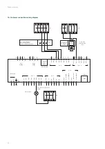
19. Customer connections wiring diagram
50
G
DO1
DO2
DO3
DO4
DO5
DO6
DO7
Agnd
A1
A3
A2
A4
Agnd
Agnd
UI1 :AI5/DI9
UI3 :AI7/DI11
UI4 :AI8/DI12
UI2 :AI6/DI10
Agnd
G
DO
1
2
3
4
10
11
12
13
14
15
16
17
30
31
32
33
34
35
40
41
42
43
44
45
G0
+C
60
B
B
A
A
N
Port 1
RS285
Port 2
RS285
Modular
conn.
4P4C
RJ45
Ext. available
TCP/IP
N
E
E
51
61
71
90
91
92
93
94
95
DI1
DI1 - 8
UI1 - 4
AI1 - 4
DO1 - 7
24V AC/DC
+
-
AO1 - 5
Agnd
AO
1
AO
2
AO
3
AO
4
AO
5
DI2
DI3
DI4
DI5
DI6
DI7
DI8
72
73
74
75
76
77
78
52
62
53
63
Alarm report *
* DO5 24 Vac output
to be
relayed.
3-way valve
(Hot water coil
only)
PV = forced low speed
GV = forchigh speed
STOP = forcedmachine stop
1 = black wire
2 = red wire
3 = white wire
OFF
PV
GV
1 2 3
T
Y
- + S
61
62
63
64
65
66
67
68
69
70
71
72
73
74
75
76
77
78
79
80
B7
B8
B9
31
32
33
34
46
47
48
49
B3

