background image

52

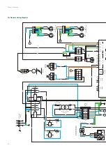
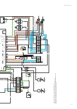
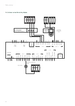
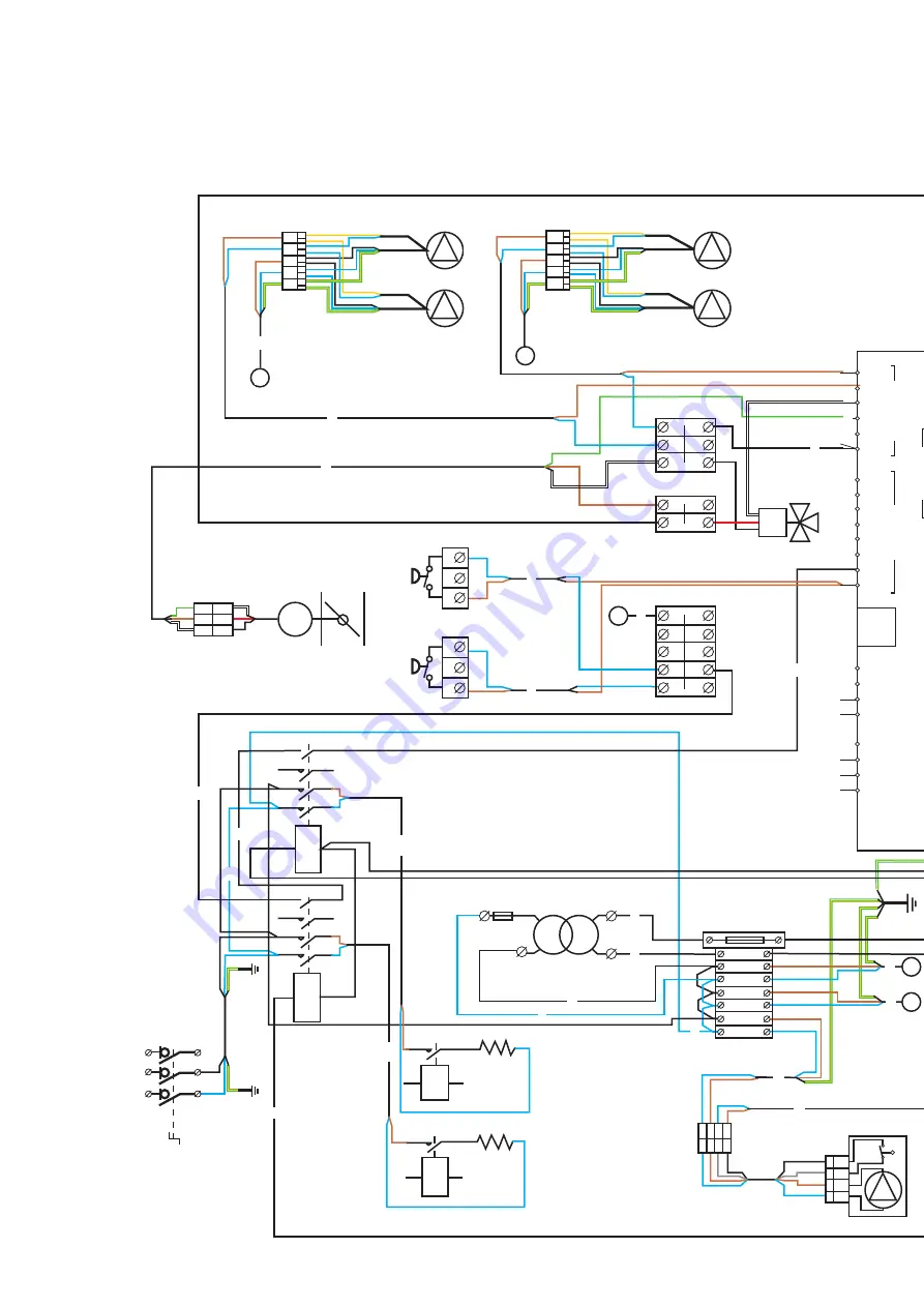
18. General wiring diagram

Zehnder Eversky

BE

4/A2

4/A2

4/A2

4/A2

3/A1

KS1

KSD

3/A1

3/A1

3/A1

C30

P4

1

1

BYP

ASS

2

2

3

3

4

4

5

5

6

6

5

14

14

13

13

230V

ac

24V

ac

K1

P2

P3

M

C4

12

VAS-2

Versions 900/1100

VAR-2

Versions 900/1100

VAS-1

VAR-1

KD

2/T1

2/T1

1/L1

1/L1

DBE

*Shunt be

tw

een (3) and

(4) if PRC no

t present

Transf

ormer

230 Vac / 24 V

ac

Integral fuse

1,0AT

P6

P7

P8

50

60

B

B

A

A

N

Por

t 1

RS285

Por

t 2

RS285

Modular conn. 4P4C

Ext. 

av

ailable

N

E

E

51

61

71

90

91

93

94

95

DI1

DI1 - 8

UI1 - 4

AO1 - 5

Agnd

AO1

AO2

AO3

AO4

AO5

DI2

DI3

DI4

DI5

DI6

DI7

DI8

72

73

74

75

76

77

78

52

62

53

63

92

PRC

J7

C18

A

B

C

17

C1

C3

J6

1 2 3 4

Fuse

terminal 3.

15A

B1

1

2

3

4

5

6

7

2

1

3

5

N

L

4

6

Disconnec

tor

switch 

1

P10

C13

P1

15

16

10

C11

17

C8

Cx

14

B7

65

64

74

63

73

62

61

72

71

75

C

1

2

3

DEP

-FS

(Op

tion)

1

2

3

DEP FS

J1

1

2

3

3-

way

valv

e

(4)

123 T

Y

-

+S

B8

66

76

77

67

68

78

69

70

79

80

B9

C9

A

C3

B

J3

1

2

3

4

5

J2

1

2

3

4

5

C1

C2

2

P5

P9

20

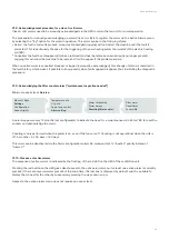
Содержание Eversky 500

Страница 1: ...always the best climate Installation Service and User Manual Decorative radiators Comfortable indoor ventilation Heating and cooling ceiling Clean air solutions Zehnder Eversky...

Страница 2: ...elayed____________________________________________________________________________________ 23 9 2 Heat demand output DO3 24 Vac to be relayed___________________________________________________________...

Страница 3: ...THA hot water coil __________________________________________________________________________ 51 17 4 1 Location_______________________________________________________________________________________...

Страница 4: ...ts is the property of Zehnder Group Any form of publication whether in whole or in part requires the written approval of Zehnder Group In house duplication designated for the evaluation of the product...

Страница 5: ...operation inspection panels doors and hatches must always be fitted and closed The unit must only be switched on and off via the proximity switch Safety and control equipment must not be removed short...

Страница 6: ...0 927 449 415 170 170 170 315 1985 555 830 900 510 1547 220 260 927 449 415 170 170 180 315 2365 615 1085 1050 530 1924 220 280 1185 510 565 170 190 220 B G1 E1 E2 T T 9 J1 J A C N A1 1 A1 1 A2 1 M 11...

Страница 7: ...5 3 8 90 160 985 80 865 445 Hot water coil Hot water coil T Configuration Input output on top 24 mm through hole diameter Configuration Side input outputs 24 mm through hole diameter Hydraulic connect...

Страница 8: ...protection 1 4 External connections A or B Power supply Condensate drainage with lifting pump hose 6x9 B Condensate drainage by gravity 10x16 pipe C Removable connection full panels 1 5 Air duct conne...

Страница 9: ...the event of damage enter precise reservations on the carrier s delivery note and notify your distributor immediately 3 2 Unpacking When unpacking the equipment check the following points Presence of...

Страница 10: ...Variable speed fans according to CO 5 Power supply to the unit 6 Characteristics of the heating coil 7 Characteristics of the de icing coil 8 Maximum absorbed current of the unit 9 Unit reference cod...

Страница 11: ...1 7 Composition 7 1 General composition The Zehnder Eversky ventilation unit consists of the following main components Detail of the composition of the ventilation unit seen from below Zehnder Eversky...

Страница 12: ...ir filter F7 additional filter option F9 10 FR Return air filter F7 11 DEPFS Pressure switch to control the fouling of the supply filter 12 RMR Motorised isolation damper return air servo motor 13 RMS...

Страница 13: ...erminal block C 4 B7 Common terminal block C 4 B8 Common terminal block G 1 24 V B9 Common terminal block AGND 90 INS1 3 Inserts for earth connection K1 Electric coil heating contactor BE KD Preheatin...

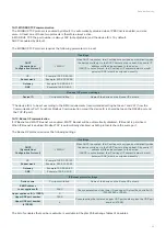
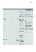
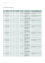
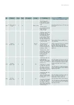
Страница 14: ...ating coil MF PV Low speed forced operation DI3 controller 73 To be connected to an external NO dry contact normally open MF GV Low speed forced operation DI4 controller 74 To be connected to an exter...

Страница 15: ...tted in the factory Particular attention should be paid when lifting it off the floor and placing it on the floor to avoid shocks that could damage the structure and integrity of the product If the un...

Страница 16: ...rge opening must be provided according to the recommendations in the following table EVERSKY A min mm E mm E1 min mm E2 min mm Min mm 500 190 1300 190 230 300 750 225 1550 225 260 350 900 225 1550 225...

Страница 17: ...ards the outside at the fresh air supply and exhaust air outlet ducts Also ensure that the building is kept watertight at the core holes between the wall and the ducts On the outside fill the gap betw...

Страница 18: ...ing nuts on the screws threaded rods of the mounting bracket the nuts should be engaged about 10 mm after the end of the screws threaded rods 3 Draw 2 marks on the ceiling 1 line 120 mm from the wall...

Страница 19: ...the position of the unit laterally using the two template plates as a guide visual marker 4 Raise the unit until it is flush with the ceiling 5 Move the unit backwards until it is resting against the...

Страница 20: ...ow the threaded rod to protrude 70 mm below the bracket Ensure that the fixing of the threaded rods in the ceiling is strong enough to support The weight of the unit itself and any options fitted to i...

Страница 21: ...1 Loosen the F screws and remove the connections 2 Turn over the connections Insert the connections into the ducts Tighten the F screws The modularity of the connections allows them to be positioned...

Страница 22: ...oned on one side and feed the power cable through it One of the grommets B is reserved for the drainage of condensate by gravity system Connect the power wires directly to the terminal block of the is...

Страница 23: ...ivated The maximum current is limited to 100 mA and must be relayed to supply a component whose consumption exceeds the maximum current The status of the digital output DO3 is associated with the stat...

Страница 24: ...tional integral control loop This signal can be used for example to control an external device modulating 3 way valve heating system etc that provides heating for the room with the central ventilation...

Страница 25: ...direction of fluid flow AB A B B A AB B AB A AB B A A AB B A B AB 72 73 74 75 62 63 64 65 B7 71 61 DI3 controller PV 9 5 Normal speed forced operation input or HS high speed DI4 The external high spee...

Страница 26: ...or RS485 communication for MODBUS RTU or BACnet MS TP protocols It is equipped with a 4 terminal screw connector Use shielded 2 pair crossed twisted cable such as BELDEN 3106A or BELDEN 3107A or equiv...

Страница 27: ...e TCP IP port at the bottom right of the controller Connecting the RJ45 Ethernet cable to the controller s IP port 9 10 HMI human machine interfaces 9 10 1 General information The Zehnder Eversky cont...

Страница 28: ...tallation rules for the condensate siphon can lead to an overflow of the condensate tray and internal flooding of the ventilation unit which can cause damage to the equipment malfunctions and may enda...

Страница 29: ...unit is switched on It is equipped with a level controller that automatically switches the pump on and off depending on the level of condensate in the tank As standard the pump incorporates a dry NC c...

Страница 30: ...formance and operating limits Maximum length 10 m Maximum height difference 5 m Maximum condensate temperature 35 C Thermal overheating protection automatic restart 115 C Overflow contact NC normally...

Страница 31: ...he rising part of the discharge pipe after cutting it off and observing the installation rules see chapter on Installation of the anti siphoning device below 7 Connect the electric cable to the termin...

Страница 32: ...the level detection chamber and clogging of the pump 2 Gently pour water into the condensate tray using a bottle 3 Check that the pump starts and stops properly to drain the spilled water If too much...

Страница 33: ...e in which it is installed Protection against icing of the recovery unit by modulating bypass At low outside air temperatures the flow rate of fresh air through the recovery unit is continuously optim...

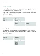
Страница 34: ...the front panel is in the ON position and the starting conditions are met the machine starts automatically If you want to stop the fan unit the Operating mode parameter must be changed from Auto to M...

Страница 35: ...e of the user interface screen Minimum access level User Access path PG ELE 011 C Ventilation prog Version 3 6 1 12 Choose language Choose language French AUTO CO MODE 2022 03 31 7 30 System Off C 26...

Страница 36: ...holiday period is defined by a start day month and an end day month Up to 24 different periods can be set By default the 1st day of the year is a day that is part of the holiday period The time period...

Страница 37: ...ould be a delay of at least 1 1 5 hours between the end of night cooling and the beginning of the room s occupancy period end of night cooling 7 00 am 3 Start the night cooling at around midnight Too...

Страница 38: ...e location This concentration is generally above 300 ppm for a non urban location and can exceed 700 ppm for a very dense urban location Increasing the fan speed and thus the airflow rate will not low...

Страница 39: ...n Exchanger de icing Ctrl CO2 VOC active If pgr on Type fans Duration min 20 min Sequential Speed 1 2 800 ppm Speed 1 1 1000 ppm Diff 160 ppm Minimum access level Operator Access path to the fan speed...

Страница 40: ...tion is set as standard to operate from 00 00 to 07 00 adjustable When the Night Cooling function is active the hot and cold outputs are deactivated the exchanger switches to fresh air An adjustable f...

Страница 41: ...rol panel in high speed The fire function will take priority over any other alarm 3 Normal operation Keeps the unit running according to the settings entered locally Off Low Speed High Speed 4 Supply...

Страница 42: ...00 600 1200 2400 4800 9600 19200 2 stop bits YES YES 2 bits NO 1 bit Parity None None even odd The maximum communication speed depends on the length and quality of the communication cable The list of...

Страница 43: ...vice ID is shared between the RS485 port and the TCP IP port 14 12 Bacnet IP communication If IP Bacnet and MS TP Bacnet are enabled MS TP Bacnet will be automatically disabled IP Bacnet is prioritise...

Страница 44: ...l Auto Settings Configuration Access rights Temperature ctrl CO2 ctrl Supp loop control Alarm setting Save user settings No Restore factory settings No Restore user settings No 15 2 Factory settings U...

Страница 45: ...oration of user settings is called and no prior backup has been made the restored settings will be the factory settings 16 1 2 Electrical connections The pressure filters are of type NO normally open...

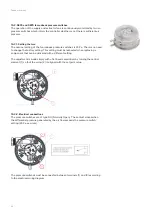
Страница 46: ...etting This setting must be respected when replacing a component that can be delivered with a different setting The adjustment is made simply with a flat head screwdriver by turning the central elemen...

Страница 47: ...ol unit of the correct operation of the fans These pressure switches are of type NO Normally Open At rest the contact is open It closes when the differential pressure exceeds the set value 25 Pa ex wo...

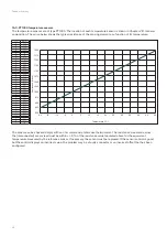
Страница 48: ...1101 25 1097 24 1093 23 1090 22 1086 21 1082 20 1078 19 1074 18 1070 17 1066 16 1062 15 1059 14 1055 13 1051 12 1047 11 1043 10 1039 9 1035 8 1031 7 1027 6 1023 5 1019 4 1016 3 1012 2 1008 1 1004 0 1...

Страница 49: ...a problem with the sensor or the connection EVERSKY L air ambiant contient naturellement une part de CO2 variable selon l endroit o l on se situe Cette concentration se situe g n ralement toujours au...

Страница 50: ...protect the electric heating and preheating coil if fitted and their immediate surroundings from excessive overheating e g in the event of a failure of a control element contactor solid state relay c...

Страница 51: ...iods of low outside temperature below 5 C When the thermostat THA triggers the contact opens the fan unit stops and the DO3 hot water pump output is activated to force the heating coil to heat up When...

Страница 52: ...P7 P8 50 60 B B A A N Port 1 RS285 Port 2 RS285 Modular conn 4P4C Ext available N E E 51 61 71 90 91 93 94 95 DI1 DI1 8 AO1 5 Agnd AO1 AO2 AO3 AO4 AO5 DI2 DI3 DI4 DI5 DI6 DI7 DI8 72 73 74 75 76 77 78...

Страница 53: ...ersion 4 A2 KS1 9 SBD SBG SSG SRG SEG C7 M RMR RMS M C C THSD 3 2 2 THA 1 THS 2 C12 G DO1 DO2 DO3 DO4 DO5 DO6 DO7 Agnd A1 A3 A2 A4 Agnd Agnd UI1 AI5 DI9 UI3 AI7 DI11 UI4 AI8 DI12 UI2 AI6 DI10 Agnd G D...

Страница 54: ...ar conn 4P4C RJ45 Ext available TCP IP N E E 51 61 71 90 91 92 93 94 95 DI1 DI1 8 UI1 4 AI1 4 DO1 7 24V AC DC AO1 5 Agnd AO1 AO2 AO3 AO4 AO5 DI2 DI3 DI4 DI5 DI6 DI7 DI8 72 73 74 75 76 77 78 52 62 53 6...

Страница 55: ...installation and operating conditions the inspection interval may be reduced The warranty will be void if the maintenance instructions are not followed Before commencing any maintenance or repair wor...

Страница 56: ...ensor has been tripped a Check that the lifting pump is working properly b Check that there is no obstruction in the condensate drain line c Check that there is a shunt between terminals 3 and 4 of co...

Страница 57: ...m It is a delay before the alarm is triggered This is a condition available for all alarms When the delay is set to 0 the alarm is not active There is no time limit to the disappearance of the cause W...

Страница 58: ...ol signal 0 10 V inverted Faulty electrical wiring connection Fan control pressure switch Faulty Poor electrical connection Poor air connection Incorrect setting nominal factory setting 25 Pa Faulty e...

Страница 59: ...t or repeated too many Start Stop cycles Set the machine for continuous operation Foreign matter or dust in the tube or pressure tap The low speed and or normal speed setpoint is too low and the fan s...

Страница 60: ...Thermostat THA Incorrect setting factory setting 5 C Faulty The water circulation pump does not work 3 way valve Defective Poor electrical connection Poor airflow connection The hot water generator d...

Страница 61: ...ery whenever the fan unit is powered Auxiliary contact of K1 blocked in open state Auxiliary contact of KD blocked in open state Faulty wiring connection on the auxiliary contact circuit of K1 Faulty...

Страница 62: ...mode In the Manual Auto menu VAR must be set to Auto 41 Heating in manual mode C 5s Doesn t stop The AO1 output for controlling the 3 way valve of the hot water heating coil is in manual mode The ala...

Страница 63: ...e programme by following the procedure see XXIII REPLACING THE INTERNAL MEMORY BATTERY 49 AS temp sensor error A 5s Off The analogue input AI1 has detected an implausible signal open circuit or short...

Страница 64: ...en the alarm is present Outputs that have been switched to manual mode must be switched back to automatic mode and the alarm manually acknowledged before the machine can be restarted In the Manual Aut...

Страница 65: ...c procedure 21 9 Acknowledging the filter counter alarm maintenance inspection needed Minimum access level Service Temperature ctrl CO ctrl Supp loop control Alarm setting Alarm thresholds Alarm delay...

Страница 66: ...ilters it is possible to reset the filter counter see XXI 9 Acknowledging the filter counter alarm maintenance inspection needed 23 Replacing the internal memory battery When the low battery alarm app...

Страница 67: ...er Eversky 750 Volume flow m h Static pressure Pa 100 200 300 500 700 0 200 300 100 400 500 600 700 11000 10000 100 90 80 70 60 50 40 400 800 900 600 Volume flow m h Static pressure Pa 100 200 300 500...

Страница 68: ...pressure Pa 100 200 300 500 1200 0 200 300 100 400 500 600 700 12000 10000 11000 100 90 80 70 60 50 40 400 800 900 600 700 800 900 1000 1100 Volume flow m h Static pressure Pa 100 200 300 500 1500 0 2...

Страница 69: ...anually in the presence of a natural person directly on the machine s HMI after having identified and resolved the cause of the problem The instructions sent by the communication have priority over al...

Страница 70: ...9 short AV 40009 Temperature of exhaust bypass management C X 10 Input Register 21 short AV 40021 Temperature of preheated air fresh air preheating coil management C X 10 Input Register 30 short AV 40...

Страница 71: ...30012 Used only if temperature supply or return is regulated by air law Setpoint of air law temperature at ext temp 5 C C X X 10 230 Holding Register 13 short AV 30013 Used only if temperature supply...

Страница 72: ...034 0 no alarm 1 alarm presents present Supply return filters fault X Input Status 38 bool BV 20038 0 no alarm 1 alarm presents present Internal battery fault X Input Status 80 bool BV 20080 0 no alar...

Страница 73: ...onstant supply air temperature Air law at supply Constant return temperature Air law at return Setpoint C Ext temp 20 0 C 15 0 C 10 0 C 5 0 C 0 0 C 5 0 C 10 0 C 15 0 C Setpoint C Ext temp 20 0 C 15 0...

Страница 74: ...MINIBLUE MINIBLUE LOBBY MAXIPLUS CITYCOOL COMBIBOX CONCEPT CMH EVENTYS CARMA NEOTIME FREETIME EXAECO HEXAMOTION SILVERTOP EVERSKY ELECTROPACK AQUAPACK LOBBY SYSTEM TOP SYSTEM DIV WONDEROOM CVFMI CVFT...

Страница 75: ...IME HEXAMOTION SILVERTOP THERMOVER EVERKIT Dual flow unit section the following standards and specifications were applied EN 1886 2008 Ventilation for buildings Air handling units Mechanical performan...

Страница 76: ...Company 1st line of address Town Country email web Z MASTER V0522 CSY BA Eversky xx nderungen vorbehalten...

Отзывы: