


035-17480-000 Rev. A (800)
Unitary Products Group
7
When the furnace is used in conjunction with a cooling coil,
the coil must be installed parallel with, or in the supply air side
of the furnace to avoid condensation in the primary heat
exchanger.
When a parallel flow arrangement is used, the dampers or
other means used to control air flow must be adequate to pre-
vent chilled air from entering the furnace, and if manually
operated, must be equipped with means to prevent operating
of either unit unless the damper is in the full heat or cool
position.
UPFLOW MODELS
Supply Plenum Connection
Attach the supply plenum to the fur-
nace outlet duct connection flanges.
This is typically through the use of S
cleat material when a metal plenum is
used. The use of an approved flexible
duct connector is recommended on all
installations. This connection should be
sealed to prevent air leakage.
If a matching cooling coil is used, it
may be placed directly on the furnace
outlet and sealed to prevent leakage.
Follow the coil instructions for installing
the supply plenum.
On all installations without a coil, a removable access panel
is recommended in the outlet duct such that smoke or
reflected light would be observable inside the casing to indi-
cate the presence of leaks in the heat exchanger. This
access cover shall be attached in such a manner as to pre-
vent leaks.
Return Duct Connection
Return air may enter the furnace through the side(s) or bot-
tom depending on the type of application. Return air may
not be connected into the rear panel of the unit. Refer to
the "Filter Installation" section of this instruction for the type of
application desired for specific installation details.
NOTE:In order to achieve the airflow indicated in the table, it
is recommended those applications over 1800 CFM use
return air from two sides, one side and the bottom or bottom
only. For single return application, see data and notes on
blower performance data tables in this manual.
FILTER INSTALLATION - UPFLOW
All applications require the use of a filter. A high velocity filter
and retainer are provided for field installation.
Internal Installation
1.
Select desired filter position (left/right side, and/or bot-
tom). Remove the corresponding cabinet cut-outs per
instructions provided.
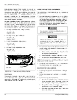
2.
Install snap-in retainer clips into the corresponding slots
from the outside rear of the cabinet (Refer to Figure 2).
To prevent cabinet air leaks, install snap-in plugs (pro-
vided) into the unused slots at the outside rear of the
cabinet.
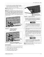
3.
Install the wire retainer inside the cabinet. Insert the
open ends of the wire retainer into the clip loops at the
rear of the blower compartment. The retainer wire should
pivot freely like a hinge, on the clips at the rear of the
cabinet. (Refer to Figure 3).
4.
Install the filter(s) provided. Cut filter if necessary to
match air opening in cabinet. Filter should extend
beyond opening edge as much as possible to prevent air
from bypassing the filter. DO NOT remove stiffening rods
from inside the filter. Shorten the rods, if necessary, to
match final filter size.
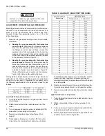
TABLE 2: UNIT CLEARANCES TO COMBUSTIBLES
(ALL DIMENSIONS IN INCHES)
All surfaces identified with the unit in an upright configuration
APPLICATION
TOP
FRONT
REAR
LEFT
SIDE
RIGHT
SIDE
FLUE
FLOOR/
BOTTOM
CLOSET
ALCOVE
ATTIC
LINE
CON-
TACT
UPFLOW MODELS (P*XU / G9D-UP)
UPFLOW
1
3
0
0
0
0
COMBUSTIBLE
YES
YES
YES
NO
FIGURE 2 :
Furnace Filter Slot Locations
FURNACE
(REAR CABINET)
RIGHT
SIDE
SLOTS
LEFT
SIDE
SLOTS
BOTTOM SLOTS
CABINET
SLOT
FILTER SUPPORT
CLIPS (PROVIDED)
PLUG UNUSED
CABINET SLOTS
WITH PLUGS
(PROVIDED)


