York P*XU/G9D-UP Скачать руководство пользователя страница 29

035-17480-000 Rev. A (800)

Unitary Products Group

29

MAINTENANCE

Air Filters

The filters must be checked periodically for dirt accumulation.
Dirty filters greatly restrict the flow of air and may cause dam-
age to the system.

Clean the filters at least every three months. On new con-
struction, check the filters every week for the first four weeks.
Inspect the filters every three weeks after that, especially if
the system is running constantly.

All filters used with the furnace are the high-velocity, clean-
able type. Clean these filters by washing in warm water.
Make sure to shake all the water out of the filter and have it
reasonably dry before installing it in the furnace. When
replacing filters, be sure to use the same size and type as
originally supplied.

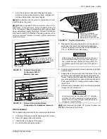
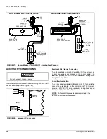
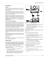
Filter Removal - Upflow Models

The ends of the retainer are attached to the rear panel in two
metal loops. (Refer to Figure 30.) The ends must be
squeezed together to free them from the loops. The retainer
may then be moved to the new location and the ends inserted
in the loops on the rear panel at the new location. Loops are
provided for retainer location to accommodate filter applica-
tion on the bottom or either side of the furnace.

To remove a filter from the bottom location, push the closed
end of the filter retainer to the left until it clears the lip on the
front of the furnace base, which acts as a catch for the
retainer. When the retainer is clear of the flange, it will pivot in
the loops.

Swing the retainer toward the center of the furnace. This will
expose the filter to allow removal. To reinstall the filter, simply
reverse this procedure.

Lubrication

Blower motors in these furnaces are permanently lubricated
and do not require periodic oiling.

BLOWER CARE

Even with good filters properly in place, blower wheels and
motors will become dust laden after long months of opera-
tion. The entire blower assembly should be inspected annu-
ally. If the motor and wheel are heavily coated with dust, they
can be brushed and cleaned with a vacuum cleaner.

The procedure for removing the direct drive blower assembly
for cleaning is as follows:

1.

Disconnect the electrical supply to the furnace and
remove the access doors.

2.

Remove blower assembly mounting screws and slide the
blower assembly out of the slots in the deck. If the two
shipping screws were not previously removed, also

remove and discard these two screws located on each
front corner of the blower assembly.

3.

To reassemble, reverse the procedure, restore power to
the furnace and verify operation.

Burner Removal/Cleaning

The main burners should be checked periodically for dirt
accumulation.

If cleaning is required, follow this procedure:

1.

Turn off the electrical power to the unit.

2.

Turn off the gas supply at the external manual shutoff
valve and loosen the ground union joint.

3.

Remove the upper access panel and remove the burner
box cover.

4.

Remove the screws that hold the burner box assembly to
the vest panel and remove the assembly.

5.

Remove burners from the burner assembly.

6.

Burners may be cleaned by rinsing in hot water.

7.

Reassemble the burners in the reverse order.

Cleaning the Heat Exchanger

1.

Turn off the main manual gas valve external to the fur-
nace.

2.

Turn off electrical power to the furnace.

3.

Remove the upper access panel and remove the burner
box cover.

FIGURE 30 :

Upflow Filter Retainer

Содержание P*XU/G9D-UP

Страница 1: ...TART UP AND ADJUSTMENTS 20 ACCESSORY CONNECTIONS 24 FURNACE ACCESSORIES 25 FILTER PERFORMANCE 26 OPERATION AND MAINTENANCE 26 TROUBLESHOOTING 30 FURNACE CONTROL DIAGNOSTICS 30 WIRING DIAGRAM UPFLOW MO...

Страница 2: ...THREE TWO PIPE SYSTEM USING COMBUSTION AIR FROM A VENTILATED ATTIC SPACE 18 HORIZONTAL VENT APPLICATIONS 18 CONDENSATE PIPING 19 SAFETY CONTROLS 19 START UP AND ADJUSTMENTS 20 IGNITION SYSTEM SEQUENCE...

Страница 3: ...ransit There are no shipping or spacer brackets which need to be removed NOTES CAUTIONS WARNINGS The installer should pay particular attention to the words NOTE CAUTION and WARNING NOTES are intended...

Страница 4: ...size as determined using the appropriate tables in Appendix G of the above codes SPECIFIC UNIT INFORMATION LIMITATIONS LOCATION This furnace should be installed in accordance with all national and lo...

Страница 5: ...leaning Eighteen 18 inches at the side where access is required for passage to the front when servicing or for inspection or replacement of flue vent connections 8 Where it will not interfere with the...

Страница 6: ...ust comply with the National Electrical Code NFPA 70 latest edition For altitudes above 2 000 ft reduce capacity 4 for each 1 000 ft above sea level Refer to Form 650 78 N1 1V Wire size based on coppe...

Страница 7: ...ls NOTE In order to achieve the airflow indicated in the table it is recommended those applications over 1800 CFM use return air from two sides one side and the bottom or bottom only For single return...

Страница 8: ...cation outside the utility room or basement For further details consult Section 5 3 Air for Combustion and Ventilation of the National Fuel Gas Code ANSI Z223 1 or CAN CGA B149 1 or 2 Installation Cod...

Страница 9: ...for 63 F 35 C rise wire when installed in accordance with instructions Refer the rating plate or Physi cal and Rating Data Tables in these instructions for specific furnace electrical data Provide a p...

Страница 10: ...mostat to the terminal board on the ignition module Connect Class 2 control wiring for single stage thermostat or for two stage thermostat Refer to Figure 7 for single stage and Fig ure 8 for two sta...

Страница 11: ...e observed Long radius elbows are required for all units 1 Long radius elbows are required for all units 2 Elbows are assumed to be 90 degrees Two 45 degree elbows count as one 90 degree elbow 3 Elbow...

Страница 12: ...e grade and anticipated snow depth 1 ft Above grade when adjacent to public walkway 7 ft From electric gas meters regulators and relief equipment min horizontal distance 4 ft Does not apply to multipl...

Страница 13: ...ional Clearance FIGURE 12 Horizontal Termination Configuration With Horizontal Extension VENT OVERHANG COMBUSTION AIR ELBOW PARALLEL TO WALL 12 SEPARATION BETWEEN BOTTOM OF COMBUSTION AIR AND BOTTOM O...

Страница 14: ...fined space is an area with less than 50 cubic feet per 1000 Btu hr input rating for all appliances installed in that area The following must be considered to obtain proper air for combustion and vent...

Страница 15: ...all be permitted to be waived where special engineering approved by the authority having jurisdiction provides an adequate supply of air for combus tion ventilation and dilution of flue gases Combusti...

Страница 16: ...nted vertical terminals may be field fabricated Standard PVC SRD fittings may be used Terminal configuration must comply as detailed in this section When selecting the locations for vent termination t...

Страница 17: ...ater tight seal 7 Support the vent piping such that it is angled 1 4 per lin ear foot so that condensate will flow back towards the furnace Piping should be supported with pipe hangers to prevent sagg...

Страница 18: ...Table 5 on page 16 Follow all notes installation procedures and required materials in the METHOD TWO ONE PIPE SYSTEM on page 14 to install the vent pipe from the unit to the outdoors VENT TERMINATION...

Страница 19: ...quiva lent pipe be field installed as drain pipe The condensate piping may be tied together with the air conditioning con densate drain if the air conditioning condensate drain line is trapped upstrea...

Страница 20: ...furnace the gas piping may be full of air In order to purge this air it is recommended that the ground union be loosened until the odor of gas is detected When gas is detected immediately retighten th...

Страница 21: ...more accurate input rate adjustment To calculate a meter correction factor use the following formula Using the information from above calculate the gas input rat ing by multiplying the number of cubi...

Страница 22: ...djustment 1 Turn off all electrical power to the system at main fuse or circuit breaker 2 Attach a manometer to the outlet pressure tap of the valve 3 Turn on power and energize main and redundant P M...

Страница 23: ...crease the rise All direct drive blowers have multi speed motors The blower motor speed taps are located in the control box in the blower compartment Refer to Figure 28 and the unit wiring label to ch...

Страница 24: ...ion of the circulating blower NOTE EAC and HUM power leads are provided in the junction box for easier installation FIGURE 27 Upflow Models P XU G9D UP Reading Gas Pressure GAS VALVE U TUBE MANOMETER...

Страница 25: ...5 1075 1060 1045 1030 1000 960 910 830 755 LOW 805 795 785 770 755 730 700 655 615 565 80 75 1600 C HIGH 1940 1905 1870 1815 1760 1700 1620 1555 1460 1305 MED 1400 1390 1380 1370 1355 1320 1285 1255 1...

Страница 26: ...urnace with 2 return openings and operating on high speed blower it is found that total sys tem static is 0 58 w c To determine the system airflow com plete the following steps 1 Obtain the airflow va...

Страница 27: ...035 17480 000 Rev A 800 Unitary Products Group 27 FIGURE 29 Sequence Timing For 50a51 243 Control...

Страница 28: ...eriod the gas valve is de energized the ignitor is turned off and the 50A51 control goes into the retry sequence The retry sequence provides a 120 second wait with inducer inter purge following an uns...

Страница 29: ...l the filter simply reverse this procedure Lubrication Blower motors in these furnaces are permanently lubricated and do not require periodic oiling BLOWER CARE Even with good filters properly in plac...

Страница 30: ...valves in the gas line to the furnace must be open 3 Make sure all wiring connections are secure 4 Review the sequence of operation Start the system by setting the thermostat above the room temperatur...

Страница 31: ...used by a number of problems blocked vent or chimney faulty inducer cracked pressure switch hose 7 FLASH This fault code indicates that flame could not be established This no light condition occurred...

Страница 32: ...NACE RELAY IGNITER GV GRD DOOR SWITCH N O SW ELEMENTARY DIAGRAM POWER SUPPLY 120 1 60 SEE NOTE 1 GRD DS C NO LS1 C 1LP COM 120V 24V SEC PRI 1T 40VA VENTOR MOTOR HSI NOTES LEGEND DOT DELAY ON TIMER FUS...

Отзывы: