34
YORK INTERNATIONAL
Remote Emergency Stop Device
If required, a remote emergency stop device can be
wired into the unit. The device should be wired into
terminals 31 and 32 (Figs. 11 and 12, pages 39 and 40)
in the microprocessor control panel.
CONTROL PANEL WIRING
All wiring to the control panel terminal block is nomi-
nal 30 VDC and must be run in shielded cable, with the
shield grounded at the panel end only. Run shielded
cable separately from mains cable to avoid electrical
noise pick-up. Use the control panel cable entry to avoid
the power cables.
The voltage free contacts must be suitable for 30 VDC
(gold contacts recommended). If the voltage free con-
tacts form part of a relay or contactor, the coil of the
device must be suppressed using a standard R/C sup-
pressor. The above precautions must be taken to avoid
electrical noise which could cause a malfunction or dam-
age to the unit and its controls.
The length of cable to these terminals must not exceed
7.5 m (25 ft.) unless an optional input isolator kit is
fitted. The optional input isolator kit uses 15 VDC (not
30 VDC).
VOLTS FREE CONTACTS
Chilled Liquid Pump Starter
Terminals 25 and 26 (Figs. 11 and 12, pages 39 and 40)
close to start the chilled liquid pump. This contact can
be used as a master start/stop for the pump in conjunc-
tion with the daily start/stop schedule.
Run Contact
Terminals 29 and 30 (Figs. 11 and 12, pages 39 and 40)
close to indicate that a system is running.
Alarm Contacts
Each system has a voltage-free change over contact
which will operate to signal an alarm condition when-
ever a system locks out, or there is a power failure. To
obtain system alarm signal, connect the alarm circuit to
volt free terminals 23 and 24 (Figs. 11 and 12, pages 39
and 40) for No. 1 System and to terminals 27 and 28
(Figs. 11 and 12, pages 39 and 40) for No.2 System.
SYSTEM INPUTS
Flow Switch
A chilled liquid flow switch of suitable type must be
connected to terminals 13 and 14 (Figs. 11 and 12, pages
39 and 40) to provide adequate protection against loss
of liquid flow.
Remote Run/Stop
Connect remote switch(es) in series with the flow switch
to provide remote run/stop control if required.
Remote Print
Closure of suitable contacts connected to terminals 13
and 18 (Figs. 11 and 12, pages 39 and 40) will cause a
hard copy printout of Operating Data/Fault History to
be made if an optional printer is connected to the RS
232 port.
Remote Setpoint Offset – Temperature
Timed closure of suitable contacts connected to termi-
nals 13 and 17 (PWM contacts) will provide remote
offset function of the chilled liquid set point if required.
See Figs. 11 and 12, pages 39 and 40 for contact loca-
tion.
Remote Setpoint Offset – Current
Timed contact closure of a suitable contact connected
to terminals 13 and 16 (PWM contacts) will provide
remote offset of EMS% CURRENT LOAD LIMIT. See
Figs. 11 and 12, pages 39 and 40 for contact location.
Installation
Содержание Millennium YCAS Series
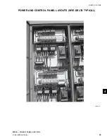
Страница 36: ...36 YORK INTERNATIONAL FIG 8 POWER PANEL SECTION CONT D OPTIONS PANEL LAYOUT TYPICAL 00246VIP Installation ...
Страница 49: ...49 YORK INTERNATIONAL FORM 201 18 NM4 7 This page intentionally left blank ...
Страница 65: ...65 YORK INTERNATIONAL FORM 201 18 NM4 LD04179 7 ...
Страница 79: ...79 YORK INTERNATIONAL FORM 201 18 NM4 This page intentionally left blank 7 ...
Страница 83: ...83 YORK INTERNATIONAL FORM 201 18 NM4 This page intentionally left blank 7 ...
Страница 87: ...87 YORK INTERNATIONAL FORM 201 18 NM4 LD04268 7 ...
Страница 119: ...119 YORK INTERNATIONAL FORM 201 18 NM4 COMPRESSOR COMPONENTS CONT D FIG 57 COMPRESSOR COMPONENTS LD03669 7 ...
Страница 120: ...120 YORK INTERNATIONAL COMPRESSOR COMPONENTS CONT D FIG 58 COMPRESSOR COMPONENTS LD03670 Technical Data ...
Страница 121: ...121 YORK INTERNATIONAL FORM 201 18 NM4 COMPRESSOR COMPONENTS CONT D FIG 59 COMPRESSOR COMPONENTS LD03671 7 ...

