170
YORK INTERNATIONAL
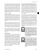
lower temperatures. If operation is occasionally needed
below -17°C (1°F), the cutout should be set at 18.0°C
(00.0°F)
This will allow operation at any temperature,
as the micro will only recognize temperatures above -
17°C (1°F). Temperatures below -17°C (1°F) will not be
displayed.
To program the Low Ambient Cutout, key in the re-
quired setting and press the Enter key to store the value
into memory and scroll to the next display.
Operation below -17°C (1°F) may oc-
casionally cause nuisance low pres-
sure safety shutdowns. This will gen-
erally not cause a problem provided
ambient temperature is not expected
to be below -17°C (1°F) for more than
a short time.
Low Leaving Liquid Temperature Cutout
The Low Leaving Liquid Temperature Cutout protects
the evaporator from damage due to ice build up caused
by operation below the chilled liquid freezing point.
If the leaving chilled liquid temperature (water or gly-
col) drops below the cutout point, the chiller will shut
down. The chiller will restart automatically when tem-
perature rises more than 2°C (4°F) above the cutout
point and cooling demand exists.
If the Dip Switch on the microprocessor board is set
for “Water Cooling” (see Section 3.7, page 150) the
cutout is automatically set at 2°C (36°F) and cannot be
reprogrammed. If the Switch is set for “Brine Cooling”
(glycol) the cutout can be programmed between -13
through -2°C (08.0 - 36.0°F). The cutout should nor-
mally be set to 2°C (4°F) below the setpoint minus the
range, i.e.
34°F (setpoint) – 2°F (range) - 4°F = 28°F
(see Section 6, page 161).
To program the Leaving Liquid Temperature Cutout, key
in the required setting and press the Enter key to store
the value into memory and scroll to the next display.
High Motor Current Unload Point
The Motor Current Unload point is used to avoid a high
motor current safety shutdown by unloading a compres-
be set to the saturated refrigerant pressure equivalent
to 10°C (18°F) below the lowest temperature of the pro-
grammed chilled liquid Control Range (Section 6). This
programmable value is password protected.
To program the Suction Pressure Cutout, key in the re-
quired setting and press the Enter key to store the value
into memory and scroll the next display.
High Ambient Temperature Cutout
The High Ambient Cutout is used to select the ambient
temperature above which the chiller may not operate.
If the ambient temperature rises 1°C (1°F) above this
point, the chiller will shut down. Restart will occur au-
tomatically, when temperature falls more than 1°C (1°F)
below the cutout and cooling demand is present.
This cutout is normally set at 54°C (130°F) to allow
operation to the absolute maximum temperature capa-
bility of the electromechanical components; however,
values between 38 - 54°C (100.0 - 130.0°F) are accepted.
This programmable value is password protected.
To program the High Ambient Cutout, key in the re-
quired setting and press the Enter key to store the value
into memory and scroll to the next display.
Low Ambient Temperature Cutout
The Low Ambient Cutout is used to select the ambient
temperature below which the chiller may not operate.
If the ambient temperature falls 1°C (1°F) below this
point, the chiller will shut down. Restart will occur au-
tomatically, when temperature rises more than 1°C (1°F)
above the cutout and cooling demand is present (see
also Section 2.5 page 143). This programmable value is
password protected.
If the SW1 Dip Switch on the Microprocessor Board
is set for “Standard Ambient Control” (see Section
3.7) the low ambient cutout is set at -4°C (25°F) and
is NOT programmable. If the Dip Switch is set for
“Low Ambient Control”, programming of the cutout
between 8 - 10°C (00.0 - 50.0°F) is allowed. This al-
lows higher values than -4°C (25° F) to be programmed
to shut down the chiller when other cooling methods
become operational. Values below -4°C (25°F) can be
used for applications requiring chiller operation at
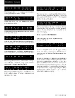
H I G H
A M B I E N T
T E M P
C U T O U T
=
5 4 . 4
° C
L O W
A M B I E N T
T E M P
C U T O U T
=
- 3 . 8 ° F
L E A V I N G
L I Q U I D
T E M P
C U T O U T
=
2 . 2 ° C
H I G H
M O T O R
C U R R E N T
U N L O A D
=
1 0 5 %
F L A
MicroPanel Contents
Содержание Millennium YCAS Series
Страница 36: ...36 YORK INTERNATIONAL FIG 8 POWER PANEL SECTION CONT D OPTIONS PANEL LAYOUT TYPICAL 00246VIP Installation ...
Страница 49: ...49 YORK INTERNATIONAL FORM 201 18 NM4 7 This page intentionally left blank ...
Страница 65: ...65 YORK INTERNATIONAL FORM 201 18 NM4 LD04179 7 ...
Страница 79: ...79 YORK INTERNATIONAL FORM 201 18 NM4 This page intentionally left blank 7 ...
Страница 83: ...83 YORK INTERNATIONAL FORM 201 18 NM4 This page intentionally left blank 7 ...
Страница 87: ...87 YORK INTERNATIONAL FORM 201 18 NM4 LD04268 7 ...
Страница 119: ...119 YORK INTERNATIONAL FORM 201 18 NM4 COMPRESSOR COMPONENTS CONT D FIG 57 COMPRESSOR COMPONENTS LD03669 7 ...
Страница 120: ...120 YORK INTERNATIONAL COMPRESSOR COMPONENTS CONT D FIG 58 COMPRESSOR COMPONENTS LD03670 Technical Data ...
Страница 121: ...121 YORK INTERNATIONAL FORM 201 18 NM4 COMPRESSOR COMPONENTS CONT D FIG 59 COMPRESSOR COMPONENTS LD03671 7 ...


