99
YORK INTERNATIONAL
FORM 150.52-NM2 (1001)
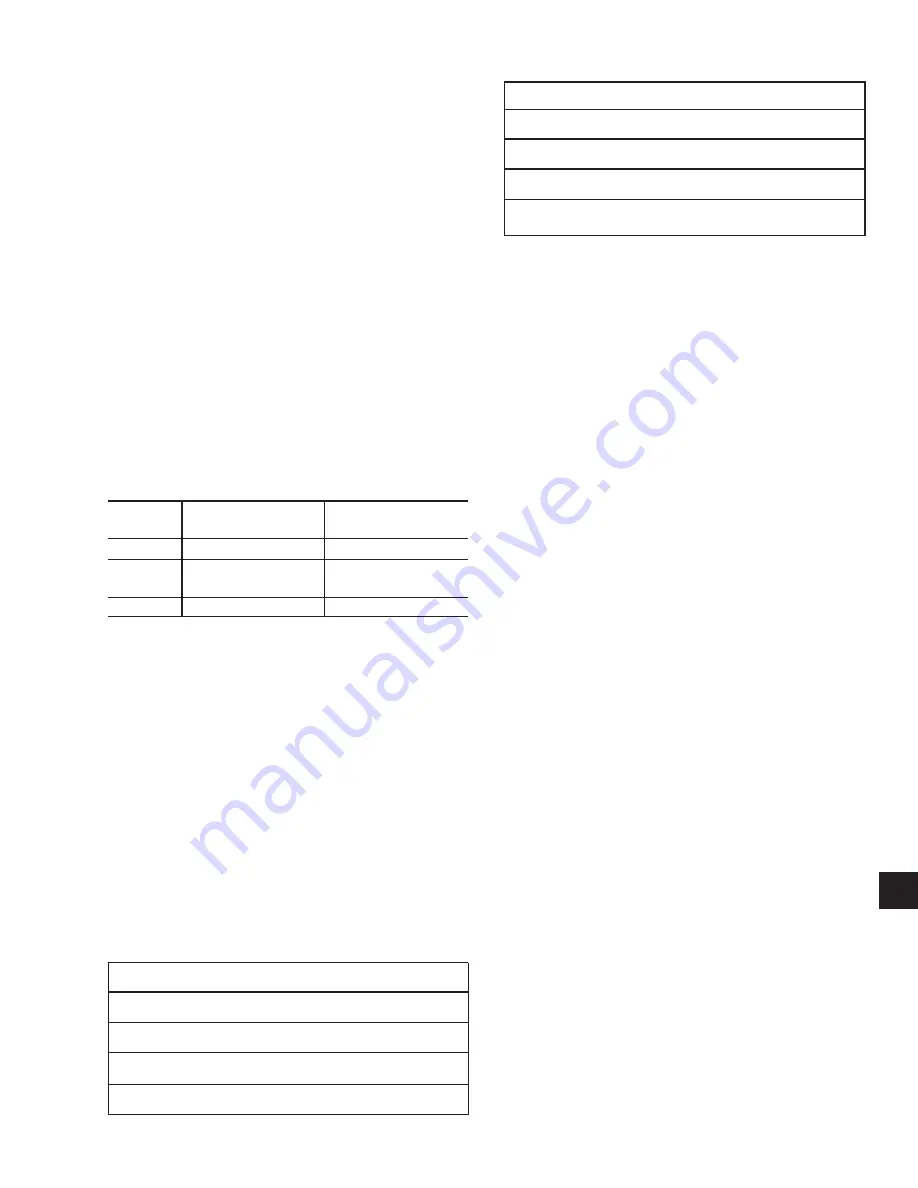
High Amb Cutout = ___________________ °C (°F)
Low Amb Cutout = ____________________°C (°F)
Leaving Chilled Liquid Temp Cutout = _____°C (°F)
High Motor Current Unload =_____________%FLA
Anti-Recycle Time = ___________________ Secs
q
6. Program the Chilled Liquid Setpoint/Range and
record:
Setpoint = ____________ °C (°F)
Range = +/– __________ °C (°F)
Keep in mind that the Target temperature dis-
played by the micro should equal the desired leav-
ing water temperature. See Section 9 (6.3), page
137 for details.
q
7. Assure that the CLK jumper J18 on the Micropro-
cessor Board is in the ON position (Top 2 pins).
See Section 9 (1.11), page 109 for location.
q
8. Set the Time and Date. See Section 9 (7.2), page
139 for details.
q
9. Program the Daily Schedule start and stop times.
See Section 9 (7.3) for details.
q
10. If Remote Reset is to be used, the maximum re-
set must be programmed under the Remote Re-
set Temp Range Key (Section 9 [6.4]).
INITIAL START-UP
After the control panel has been programmed and the
compressor heater has been on for 24 hours prior to
start-up, the chiller may be placed into operation.
q
1. Place the System Switches on the Microproces-
sor Board to the ON position.
q
2. The compressor will start and a flow of liquid should
be noted in the liquid indicator. After several min-
utes of operation, the bubbles will disappear and
there will be a solid column of liquid when the unit
is operating normally. On startup, foaming of the
oil may be evident in the compressor oil
sightglass. After the water temperature has been
pulled down to operating conditions, the oil should
be clear. Normal operation of the unit is evidenced
by: a hot discharge line (discharge superheat
should not drop below 10°C [50°F]); clear oil in
the compressor crankcase; solid liquid refriger-
ant in the liquid indicator; and, usually no more
than 13.8 kPa (2 PSIG) variation in suction pres-
sure for any given set of operating conditions.
PANEL CHECKS
(Power ON – Both System Switches “OFF”)
q
1. Apply 3-phase power and verify its value (See Fig.
8, page 36).
q
2. Apply 115VAC and verify its value on the terminal
block in the lower left of the Power Panel. Make
the measurement between terminals 5 and 2 of
TB1 (See Fig. 8, page 36). The voltage should
be /- 10%.
q
3. Assure the heaters on each compressor are on.
Allow the compressor heaters to remain on a mini-
mum of 24 hours before startup. This is important
to assure that no refrigerant is in the compressor
oil at start-up!
q
4. Program the dip switches on the microprocessor
board for the desired operating requirements. See
Section 9 (3.7), page 124. OPEN = Left side of
switch pushed down. CLOSED = Right side of
switch pushed down.
Verify the selections by pressing the OPTIONS
Key on the control panel. Check them off.
CAUTION: Damage to the chiller could result
if switches are improperly pro-
grammed.
NOTE:
Dip switches 4 through 8 are spares
and have no function.
q
5. Program the required operating values into the
micro for cut-outs, safeties, etc. and record them
in the chart below. See Page 142 for details.
If Default Values are desired for programming con-
venience, press the PROGRAM key, 6140, and
ENTER. This loads default values. Record these
values in the chart below.
PROGRAMMED VALUES
Refrigerant Type = __________________________
Dischg Press Cutout = ____________ kPa (PSIG)
Disch Press Unld = _______________ kPa (PSIG)
Suction Press Cutout = ____________ kPa (PSIG)
SWITCH
SWITCH “OPEN”
SWITCH “CLOSED”
SETTING
SETTING
1
Water Cooling
Brine Cooling
2
Standard Ambient
Low Ambient
Control
Control
3
Refrigerant R-407C
Refrigerant R-22
8


