
8-12
<Toc> <Ind>
TI 05C01E02-01E
1st Edition : Oct. 31, 2001-00
8.4 Hardware Specifications
•
Input: 1 point
•
Input type: Universal; can be selected by software
•
Input accuracy (at 23 –2
°
C
ambient temperature)
•
Thermocouple: –2¡C
However,
•
–4
°
C
for thermocouple input —200 to —100
°
C
•
–3
°
C
for thermocouple input —100 to 0
°
C
•
–5
°
C
for types R and S (–9
°
C
for 0 to 500
°
C
)(For UT150/UT152/UT155 only)
•
–9
°
C
for type B (accuracy is not guaranteed for 0 to 400
°
C
)(For UT150/UT152/UT155 only)
•
RTD: –1
°
C
–1digit
•
Voltage(mV, V) : –0.3% (For UT150/UT152/UT155 only)
•
Sampling period for measured value input: 500ms
•
Burn-out detection: Functions for thermocouple or RTD input (burn-out upscale only; cannot be switched off)
•
Input resistance: 1M‰ or greater for thermocouple or DC mV input.
Approx. 1M‰ for DC V input (For UT150/UT152/UT155 only)
•
Maximum allowable signal source resistance : 250‰ for thermocouple or DC mV input
2k‰ for DC V input
•
Maximum allowable wiring resistance for RTD input:
10W/wire (The resistance values of three wires must be the same.)
•
Allowable input voltage: –10V DC for thermocouple or DC mV input, –20V DC for DC V input(For UT150/UT152/UT155 only)
•
Noise rejection ratio: Normal mode noise: Min. 40dB
(50/60Hz)
Common mode noise: Min. 120dB
(Min. 90dB for DC V input) (For UT150/UT152/UT155 only)
•
Error of reference junction compensation: –1.5
°
C
(at 15-35
°
C
), –2.0¡C (at 0-50
°
C
)
The reference junction compensation cannot be switched off.
•
Applicable standards:
Thermocouple and resistance temperature detector JIS/IEC/DIN (ITS90)
•
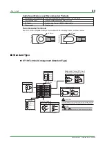
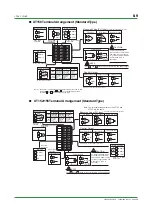
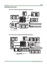
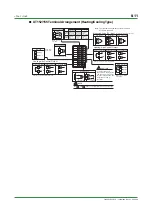
Output: 1 point (for standard type) or 2 points (for heating/cooling type)
•
Output type: Choose one from (1) to (3) below:
(1) Relay contact output
Contact capacity: 3A at 240V AC or 3A at 30V DC (with resistance load)
Note: The control output relay cannot be replaced by users.
(2) Voltage pulse output
On voltage: 12-18V DC load resistance: 600W or greater
Off voltage: 0.1V DC or less short-circuit current: approx. 30mA
(3) Current output (For UT150/UT152/UT155 only)
Output signal: 4 to 20mA
Maximum load resistance: 600‰
Output accuracy: –0.3% of span (at 23–2
°
C
ambient temperature)
Measured Value (PV) Input
Alarm Functions
Control Output
The retransmission output is provided only when the /RET option is specified, but
is not available for the heating/cooling type.
•
Output signal: Measured value in 4-20mA DC
•
Maximum load resistance: 600‰
•
Output accuracy: –0.3% of span (at 23–2
°
C
ambient temperature)
Retransmission Output (For UT150/UT152/UT155 only)
•
Safety: Confirms to IEC1010-1: 1990 and EN61010-1: 1992
Approved by CSA1010 for installation category CAT II (IEC1010-1) , Certified for UL508
•
EMC standards: Complies with EN61326
The UT130 and UT150 series temperature controllers conform to the standards
specified under the following conditions.
•
All wires except those for the power supply and relay contact output terminals are
shielded.
•
The controller does not fluctuate more than 20% even when noise is applied.
Safety and EMC Standards
The communication function is provided only when the /RS option is specified. (For details,
read the instruction manual of the communications functions IM 05C01E12-10E.)
Communication Protocol
•
Personal computer link: Used for communication with a personal computer, or UT link
module of the FA-M3 controller (from Yokogawa Electric Corporation).
•
Ladder communication: Used for communication with a ladder communication module of the
FA-M3, or a programmable controller of other manufacturers.
•
MODBUS communication: Used for communication with equipment featuring the MODBUS protocol.
Communication Interface
•
Applicable standards: Complies with EIA RS-485
•
Number of controllers that can be connected: Up to 31
•
Maximum communication distance: 1,200m
•
Communication method: Two-wire half-duplex, start-stop synchronization, non-procedural
•
Baut rate: 2400, 4800, or 9600 bps
Communication Function
Normal Operating Conditions
•
Warm-up time: At least 30 minutes
•
Ambient temperature:0-50
°
C
(0-40
°
C
when mounted side-by-side)
•
Rate of change of temperature: 10
°
C
/h or less
•
Ambient humidity: 20-90% RH (no condensation allowed)
•
Magnetic field: 400A/m or less
•
Continuous vibrations of 5 to 14Hz: Amplitude of 1.2mm or less
•
Continuous vibrations of 14 to 150Hz: 4.9m/s
2
(0.5G) or less
•
Short-period vibrations: 14.7m/s
2
(1.5G) for 15 seconds or less
•
Shock: 98m/s
2
(10G) for 11 milliseconds or less
•
Mounting angle: Upward incline of up to 30 degrees; downward incline is not allowed.
•
Altitude: 2000m or less above sea level
Maximum Effects from Operating Conditions
(1) Temperature effects
•
Thermocouple, DC mV and DC V input: –2 V/
°
C
or –0.02% of F.S./
°
C
,
whichever is larger
•
Resistance temperature detector: –0.05
°
C
/
°
C
•
Analog output: –0.05% of F.S./
°
C
(2) Effect from fluctuation of power supply voltage (within rated voltage range)
•
Analog input: –0.2 V/V or –0.002% of F.S./V, whichever is larger
•
Analog output: –0.05% of F.S. /V
Transportation and Storage Conditions
•
Temperature: —25 to 70
°
C
•
Humidity: 5 to 95% RH (no condensation allowed)
•
Shock: Package drop height 90cm (when packed in the dedicated package)
Environmental Conditions
Alarm Functions (Option Code /AL or /HBA)
•
Alarm types: 22 types (waiting action can be set by software):
PV high limit, PV low limit, Deviation high limit, Deviation low limit, De-
energized on deviation high limit, De-energized on deviation low limit, Deviation
high and low limits, High and low limits within deviation, De-energized on PV
high limit, De-energized on PV low limit, Fault diagnosis output, FAIL output
•
Alarm output: 2 relay contacts
Relay contact capacity: 1A at 240V AC or 1A at 30V DC (with resistance load)
Note: The alarm output relays cannot be replaced by users.
Heater Disconnection Alarm (Option Code /HBA)
The heater disconnection alarm is available when time-proportional PID
control or on/off control is selected.
•
Heater current setting range: 1 to 80A
•
Alarm output: 1 relay contact
(The terminals are the same as those of the /AL option.)
•
On time of burn-out detection: Min. 0.2 second
•
Sensor: CTL-6-S-H or CTL-12-S36-8 (URD Co., Ltd.)
To be purchased separately.
Timer Function (Option Code /AL/EX or /HBA/EX)
(For UT150/UT152/UT155 only)
The output contact status changes when the preset time has passed since external
contact (TMR) turned on.
The contact action can be selected by software from:
(1) Make contact—the contact closes upon time-up.
(2) Break—the contact opens upon time-up.
•
Input contact type: See the
Contact Inputs
below.
Construction, Mounting, and Wiring
•
Construction: Splash-proof front panel (compliant with IP65 [Models UT130
and UT150] and IP55 [Models UT152 and 155]). Splash-proof construction
is not available if the controller is mounted closely side-by-side.
•
Casing: ABS resin and polycarbonate
•
Case color: Black
•
Mounting: Flush panel mounting
•
Terminals: Screw terminals
Power Supply and Isolation
Power Supply
Note 1: The primary terminals are the power supply terminals and relay output terminals.
The secondary terminals are the analog input and output terminals, the voltage pulse output
terminals, and the contact input terminals.
Note 2: The withstanding voltage is specified as 2300 V AC per minute to provide a margin of safety.
Note 3: AC/DC 24V terminals are secondary terminals.
Maximum power consumption
Voltage
Frequency
Between primary terminals and secondary terminals
(See notes 1 and 3.)
Between primary terminals and secondary terminals
(See notes 1 and 3.)
Rated at 100-240VAC (–10%)
AC/DC 24V when /V24 is specified.
50/60Hz
8VA max. (4W max.)
3W max. when /V24 is specified.
Non-volatile memory
1500V AC for 1 minute (See note 2.)
20M‰ or more at 500V DC
Memory
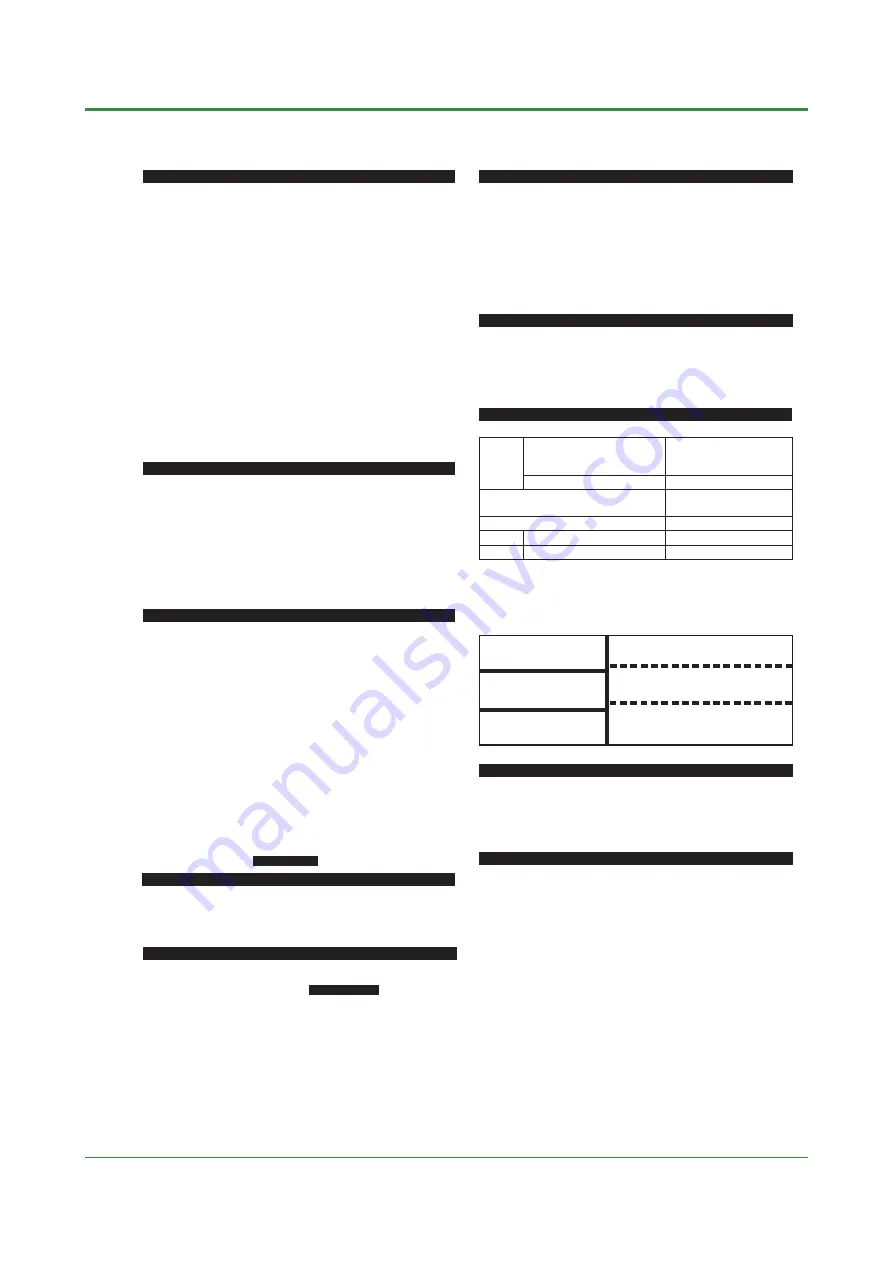
Isolation
The bold lines below indicate reinforced isolation, and the broken line indicates functional isolation.
Note: Neither the measured value input terminals, CT input terminals for the /HBA option, nor 2
input terminals for the /EX option are isolated from the internal circuit.
•
Measured value input terminals
•
CT input terminals for /HBA
•
2 input terminal for /EX
•
Internal circuit
•
Power supply
terminals
(100-240V AC)
•
Control output
terminals
(relay contacts)
•
Alarm output
terminals
(2 relay contacts)
•
Control output terminals: 4-20 mA/Voltage pulse
•
RS-485 terminals for /RS
Contact Inputs (For UT150/UT152/UT155 only)
The contact inputs are provided only when the /EX option is specified.
•
Functions: (1) SP1/SP2 switching
(2) Starting a timer (See the
Alarm Functions
.)
(3) RUN/STOP switching
Can be selected by parameter DIS.
•
Input: 2 points (with the shared common terminal)
•
Input type: Non-voltage contact or transistor contact input
•
Contact capacity: At least 12V/10mA
Insulation
resistance
Withstanding
voltage
Power
supply
•
Power supply terminals AC/DC 24V
(When /V24 is specified)
]
[
Содержание UT130
Страница 2: ...Blank Page ...
Страница 4: ...Blank Page ...
Страница 8: ...Blank Page ...
Страница 30: ...Blank Page ...
Страница 48: ...Blank Page ...
Страница 60: ...Blank Page ...
Страница 72: ...Blank Page ...


