<Toc> <Ind>
5-9
TI 05C01E02-01E
1st Edition : Oct. 31, 2001-00
•
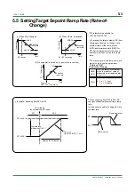
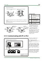
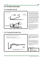
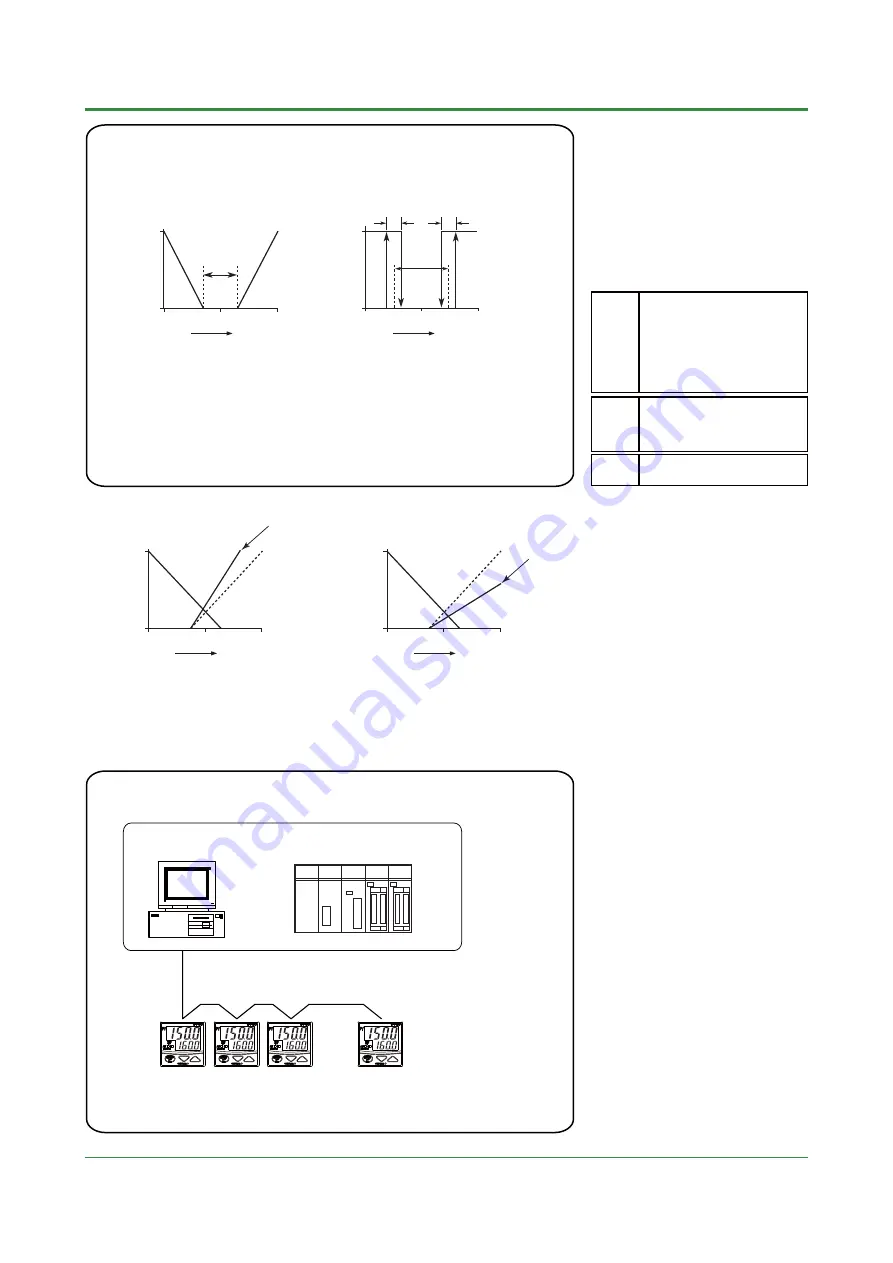
Dead band and hysteresis
In a positive dead band, there are neither heating-side nor cooling-side
outputs.
In a negative dead band, there are both heating-side and cooling-side outputs,
which overlap each other.
Dead band(+)
0
SP
100
PV
100%
Heating
Cooling
100%
Heating/cooling
MV output
(%)
0%
1. When the dead band in heating/cooling sides is positive
(P control)
HYS
HYS
ON
OFF
ON
OFF
Dead band(+)
0
SP
PV
100%
100
Heating/cooling
MV output
2. When both the heating and cooling sides are
under on/off control.
< PID control >
— (Proportional band setting) to
+ (proportional band setting)
<On/off control>
—50% to +50% of measured
input range (scale) span
DB
Parameter Range
0
°
C
/
°
F
to the temperature
corresponding to 100% of
measured input range (scale)
span
HYS
0.01 to 9.99 times
COL
0
SP
100
PV
100%
Heating-side
proportional band
= P
Cooling-side
proportional band
= P x 1.0
Cooling-side
proportional band
= P x COL
(COL > 1)
100%
Heating/
cooling
MV output
(%)
0%
0
SP
100
PV
100%
Heating-side
proportional band
= P
Cooling-side
proportional band
= P x 1.0
Cooling-side
proportional
band
= P x COL
(COL < 1)
100%
Heating/
cooling
MV output
(%)
0%
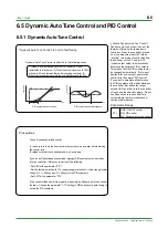
•
For example, if you set COL=2.0 and
the heating-side output is 10% at a
certain deviation (SP — PV), then the
cooling-side output will be 20% when
the cooling-side also reaches that
deviation (reverse).
•
Heating-side proportional band =
Parameter "P" (proportional band)
Cooling-side proportional band =
Parameter "P" x Parameter "COL"
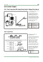
5.13 Communicating with PC or PLC
•
This function is available for the
controller with the "/RS" option.
•
For communicating with a PC,
RS232C/RS485 converter (model ML1) is
necessary.
•
Communication with a PLC (FA-M3)
manufactured by Yokogawa is through
ladder communication module (F3RZ91-
0N) or personal computer link module
(F3LC11-2N). The communication
protocol is ladder or personal computer
link.
•
Communication with a PLC (MELSEC)
manufactured by Mitsubishi is through
computer link unit (A1SJ71C24-R24 or
A1SJ71C24-R4). The communication
protocol is non-procedural ladder.
•
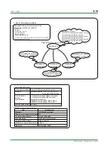
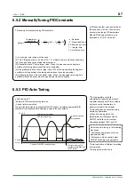
Connection Example for Communication
Maximum overall cable length of 1200m for a maximum of 31 substations
Personal computer
or
ADR=1
ADR=50 ADR=10
ADR=20
ADR = Address number for communication
The address number is the number of the
controller itself.
Any number of 1 to 99 may be assigned.
The same number can not be assigned.
RS485
Communication
PLC(FA-M3, MELSEC etc.)
Содержание UT130
Страница 2: ...Blank Page ...
Страница 4: ...Blank Page ...
Страница 8: ...Blank Page ...
Страница 30: ...Blank Page ...
Страница 48: ...Blank Page ...
Страница 60: ...Blank Page ...
Страница 72: ...Blank Page ...

