


<Toc> <Ind>
5-11
TI 05C01E02-01E
1st Edition : Oct. 31, 2001-00
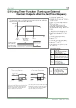
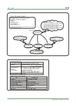
•
The details of UT100 Series
communication functions need to be the
same as those of the communication
functions of the host devices to be
connected.
•
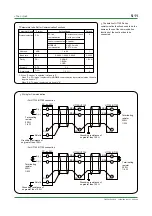
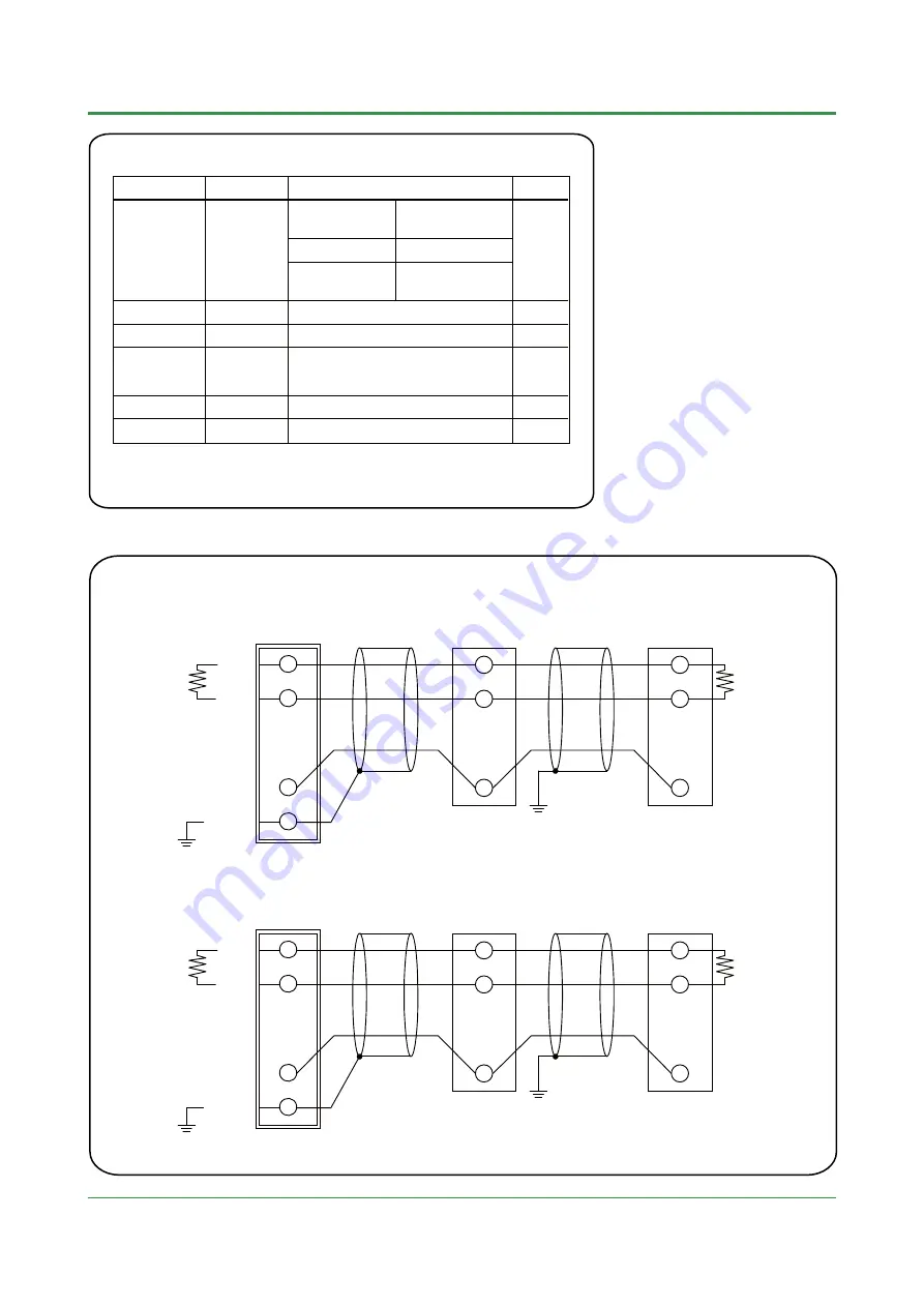
Parameters to be Set for Communication Functions
Parameter Name
MODBUS
communication
3: ASCII mode
4: RTU mode
2: Ladder
Protocol selection
PSL
0: without sum check
1: with sum check
PC link
communication
0
Symbol
Setting Range
Default
Baud rate
BPS
0: 2400, 1: 4800, 2: 9600
Parity
PRI
0: NONE
1: EVEN
2: ODD
Stop bit
STP
1, 2
Data length
DLN
7, 8 (*1)
Address
ADR
1 to 99
Ladder communication
2: 9600
1: EVN
1
8
1
*1: When "2: Ladder" is selected, it is fixed to "8".
When "3: ASCII mode" is selected for MODBUS communication in protocol selection, the data
length is fixed to "7".
When "4: RTU mode" is selected, it is fixed to "8".
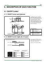
B(+)
A(—)
Shield
RSB (+)
RSA (—)
RSB (+)
RSA (—)
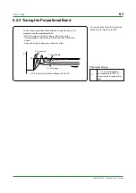
UT130/UT150
UT130/UT150
PC, or PLC
Grounding resistance of
no greater than 100
Ω
Grounding resistance of
no greater than 100
Ω
Terminating
resistor
220
Ω
1/4 W
Terminating
resistor
220
Ω
1/4 W
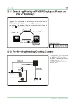
•
For UT130/UT150 connection
3
4
5
3
4
5
SG
SG
SG
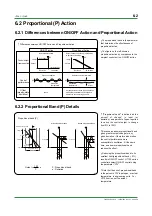
B(+)
A(—)
Shield
RSB (+)
RSA (—)
RSB (+)
RSA (—)
UT152/UT155
UT152/UT155
PC, or PLC
Grounding resistance of
no greater than 100
Ω
Grounding resistance of
no greater than 100
Ω
Terminating
resistor
220
Ω
1/4 W
Terminating
resistor
220
Ω
1/4 W
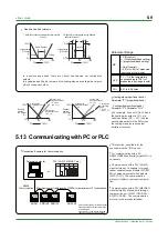
•
For UT152/UT155 connection
26
27
28
26
27
28
SG
SG
SG
•
Wiring for Communication
Содержание UT130
Страница 2: ...Blank Page ...
Страница 4: ...Blank Page ...
Страница 8: ...Blank Page ...
Страница 30: ...Blank Page ...
Страница 48: ...Blank Page ...
Страница 60: ...Blank Page ...
Страница 72: ...Blank Page ...


