
8-10
<Toc> <Ind>
TI 05C01E02-01E
1st Edition : Oct. 31, 2001-00
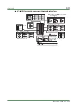
■
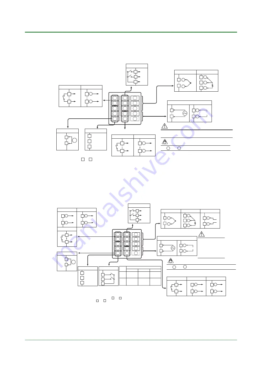
Heating/Cooling Type
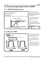
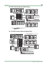
●
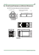
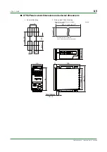
UT130 Terminal Arrangement (Heating/Cooling Type)
1
2
3
4
5
6
7
8
9
10
11
12
13
14
15
TC Input
RTD Input
Measured Value (PV) Input
Universal input-selectable input type
7
8
6
7
8
+
—
B
b
A
RS-485
3
4
5
ALM2
ALM1
COM
RSB(+)
RSA(—)
SG
Heater Current Detection Input
Alarm Outputs
When /AL or /HBA
is specified.
When /HBA is specified.
When /RS is specified.
3
4
11
12
13
NO
COM
Relay Contact Output Voltage Pulse Output
Heating-side Control Output
Specify one for the output signal type.
14
15
14
15
+
—
NO
COM
Specify one for the output signal type.
Relay Contact Output Voltage Pulse Output
Cooling-side Control Output
1
2
+
—
1
2
CT
¥ The heater current detection input terminals
are defined as terminals and for a
heating/cooling type.
¥ You are not allowed to specify both the
/HBA and /RS options at the same time.
3
4
Power Supply
9
L
N
10
9
10
AC/DC 24V
100-240V AC
+
—
When /V24
is specified.
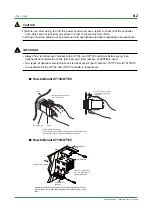
CAUTION
To prevent damage to the controller,never provide 100-240V AC power
supply for power supply AC/DC 24V model (when /V24 is specified).
NOTE
The and stand for the polarityfor DC 24V power supply.
+
—
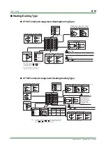
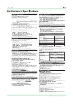
●
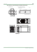
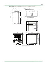
UT150 Terminal Arrangement (Heating/Cooling Type)
1
2
3
4
5
6
7
8
9
10
11
12
13
14
15
TC Input
DC mV or V Input
RTD Input
Measured Value (PV) Input
7
8
7
8
6
7
8
+
—
+
—
B
b
A
ALM2
ALM1
COM
Alarm Outputs
When /AL or /HBA
is specified.
RS-485
3
4
5
RSB(+)
RSA(—)
SG
When /RS is specified.
11
12
13
NO
COM
Relay Contact Output
4 to 20 mA DC Output
Voltage Pulse Output
Heating-side Control Output
Specify one for the output signal type.
14
15
14
15
+
—
14
15
+
—
NO
COM
Specify one for the
output signal type.
Relay Contact Output
4 to 20 mA DC Output
Voltage Pulse Output
Cooling-side Control Output
1
2
+
—
1
2
1
2
+
—
(Note 1)
Heater Current Detection Input
3
4
CT
When /HBA is specified.
Note 1: The heater current detection input terminals (option code: /HBA)
are defined as terminals and for a standard type and as
terminals and for a heating/cooling type.
1
2
3
4
To prevent damage to
the controller, never
provide 100-240V AC
power supply for power
supply AC/DC 24V
model (when /V24 is
specified).
CAUTION
External Contact Inputs
3
4
5
SP2
STOP
TMR
STOP
COM
When /EX is specified.
Parameter DIS
SP1/SP2
switching
SP2
when DI=ON
2
1
0 (Default)
TMR
STOP
SP2
STOP
RUN/STOP
switching
STOP
when DI=ON
RUN/STOP
switching
STOP
when DI=ON
SP1/SP2
switching
SP2
when DI=ON
Timer starts
when DI=ON
Timer stops
when DI=OFF
Timer starts
when DI=ON
Timer stops
when DI=OFF
9
L
N
10
Power Supply
9
10
AC/DC 24V
100-240V AC
When /V24
is specified.
+
—
NOTE
The and stand for the polarityfor DC 24V power supply.
+
—
Universal input-selectable input type
Содержание UT130
Страница 2: ...Blank Page ...
Страница 4: ...Blank Page ...
Страница 8: ...Blank Page ...
Страница 30: ...Blank Page ...
Страница 48: ...Blank Page ...
Страница 60: ...Blank Page ...
Страница 72: ...Blank Page ...


