YOKOGAWA AQ2160-02 Скачать руководство пользователя страница 25


17

2-4-2  Memory Measurement Mode 

Data measured in normal measurement mode and setting 
conditions can be saved in the instrument’s memory.    Also, you can 
display saved data (addresses and measured data only). 
Measurement continues even while data saved in memory is being 
displayed. 


 Standard Memory and User Memory 

This instrument has two types of memory.     

 Standard memory: holds up to 1000 data. 

The address are 000 to 999.     

 User memory: holds up to 100 data. 

The address are U00 to U99.     


User memory is available for storing important data and settings.   
We recommend that you use user memory for critical data that 
you wish to keep from being easily deleted.    The procedure for 
saving and recalling data is slightly different for standard memory 
and user memory.     


2-4-3    Detailed Display Mode (Memory Recall Mode) 

Details on measured data saved in memory or settings can be 

displayed in this mode.  Also, saved measurement conditions can 
be loaded and applied to the next measurement. 


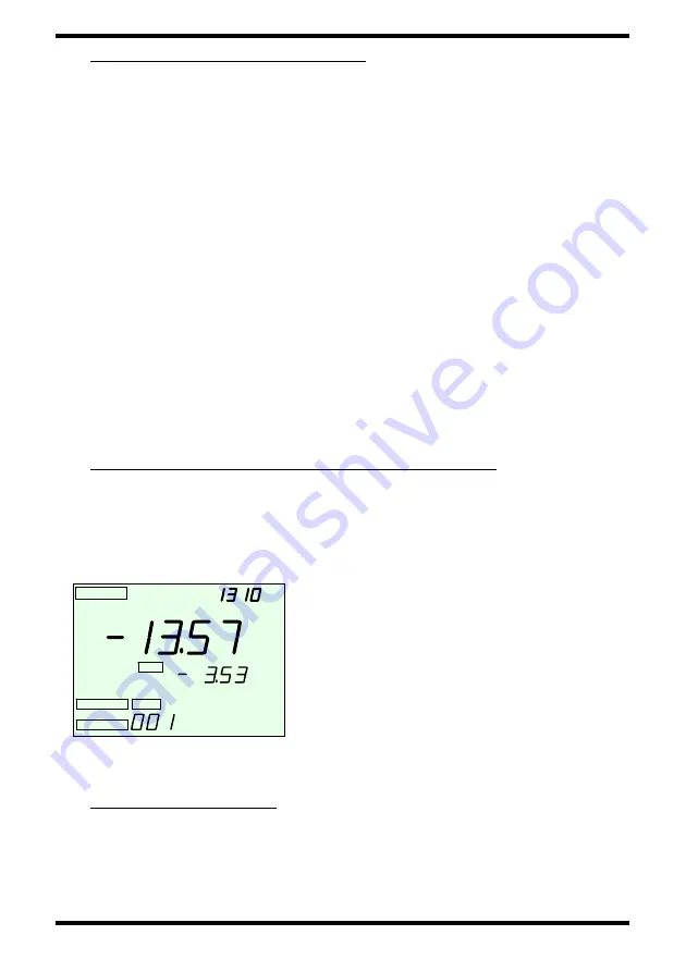
<Display Example>    Detailed Display (Memory Recall) 


DETAIL and ADRS are displayed, 
indicating the mode in which measured 
data saved to memory is displayed in 
detail.    In the example, the data saved in 
address 001 is -13.57 dB, which is the 
value relative to the reference value of 
-3.53 dBm.     


2-4-4  Data Clear Mode 

Clears data saved to memory.     
You can delete one data at a time (ONE), or all data (ALL).


DETAIL

PWR SAVE

ADRS

REF

nm

CW

dBm

dB

MEMORY


DETAIL

PWR SAVE

ADRS

REF

nm

CW

dBm

dB

DETAIL

DETAIL

PWR SAVE

PWR SAVE

ADRS

ADRS

REF

REF

nm

CW

dBm

dB

MEMORY

MEMORY


Содержание AQ2160-02

Страница 1: ...User s Manual IM SU1005A 01E 3rd Edition Model SU1005A AQ2160 02 Optical Powermeter ...

Страница 2: ...tions 8 1 8 Periodic Calibration 9 2 Explanation of Function 10 2 1 Names of Parts 10 2 2 Keys 11 2 3 Screens 13 2 4 Mode 15 2 4 1 Normal Measurement Mode 16 2 4 2 Memory measurement Mode 17 2 4 3 Detailed Display Mode Memory Recall Mode 17 2 4 4 Data Clear Mode 17 2 4 5 USB Mode 18 2 5 Other Functions 19 2 5 1 Backlight 19 2 5 2 Power Save 19 2 5 3 Battery Check 20 2 5 4 Resume 20 2 5 5 System Re...

Страница 3: ...r Measurement Absolute Value Measurement 33 3 5 Loss Measurement Relative Value Measurement 34 3 5 1 Setting the Displayed Measured Value as the Reference Value 34 3 5 2 Setting an Arbitrary Value as the Reference Value 35 3 6 High Power Measurement 36 3 6 1 Measuring after Editing the CAL Value 37 3 6 2 Measuring after Automatic Setting of the CAL Value 38 3 6 3 Clearing the CAL Value 39 4 Saving...

Страница 4: ...e 59 9 2 Precautions When Using the Batteries 60 9 3 Precautions When Using the AC Adapter 61 9 4 Disposing of the Instrument 61 10 If You Suspect a Malfunction 61 10 1 The instrument doesn t work when the power is ON 61 10 2 Normal measured values are not displayed 62 10 3 Cannot transfer data via USB 62 10 4 When the instrument starts up the backlight automatically blinks and does not stop 62 10...

Страница 5: ...censee without any objection and reservation accepts and agrees to any and all of the terms and conditions of this Agreement Yokogawa grants the Licensee the right to use one 1 copy of the software of Yokogawa set forth in Appendix A attached hereto hereinafter referred to as the Software free of charge and subject to the terms and conditions of this Agreement 2 Terms and Conditions of License 1 Y...

Страница 6: ...mply with the terms and conditions of this Agreement in order to use such up grade or revision up 5 Intellectual Property Infringement When any third party should demand injunction initiate a law suit or demand damages under patent right utility model right design patent right trademark right copyright and or any other rights relating to any of the Software including related materials or when at Y...

Страница 7: ...t re export or transmit whether directly or indirectly the Software its related documents and technical information and any derivative and result which are created through the use of the Software without observation of the export control laws and regulations of Japan and other related countries or without acquisition of necessary re export or import license at the Licensee s responsibility 9 Termi...

Страница 8: ...itration Association The award rendered by the arbitrator s shall be final and binding upon the parties hereto and any right of judicial review by or appeal or application to courts of or in any country land nation state commonwealth or region or under any jurisdiction with respect to any question of laws in the course of the arbitration or out of the award shall be excluded 13 Entire Agreement Th...

Страница 9: ...ent as much as possible entry of incorrect settings it allows even first time users to operate the instrument with confidence 1 3 Warranty Prior to shipment all Yokogawa products must pass strict testing based on the Yokogawa Quality Assurance System However should any damage occur during manufacturing or shipping that becomes evident during normal use please contact the sales office at our headqu...

Страница 10: ...eparately Name Model Specifications 1 Connector adapter for the AQ2160 02 SU2004A SCC FCC STC LCC MUC SC FC ST LC MU 2 Protector SU2002A for the AQ2160 3 AC adapter SU2007A M C F G J PSE conforming type 2 pin UL CSA standard type UL2P VDE standard type CEE C2 AS standard type AS2P BS standard type BS2P angle 4 Soft carrying case SU2006A 1 5 Trademarks Microsoft Windows and Windows XP are trademark...

Страница 11: ...sult of incorrect operation Indicates actions or situations that are likely to result in imminent death or serious injury Indicates actions or situations that can lead to death or serious injury Indicates actions or situations that can lead to loss of data or physical damage to instruments The following explains warning symbols that must be adhered to Prohibited indicates prohibition of a particul...

Страница 12: ...heat and cause fire Do not bring the power cord near any hot objects The coating on the cord can deteriorate causing fire or electric shock Do not impair damage or attempt to modify the power cord Fire or electric shock can result Never place spent batteries in fire Explosion fire or burns can result Do not insert or drop any metal objects into any openings on the instrument or inside the instrume...

Страница 13: ...ord always pull by the plug never pull by the cord itself Pulling the power cord can cause damage leading to fire or electric shock Always unplug the power cord from the outlet and check that all externally connected wires and cables are removed before moving the instrument Otherwise the cords can become damaged causing fire or electric shock For safety always unplug the power cord from the outlet...

Страница 14: ...ds or metallic objects on top of the instrument If water or metal objects spill onto or enter the instrument fire electric shock or malfunction can result Do not allow water or condensation to contact the instrument Fire electric shock or malfunction can result If you detect any abnormal conditions such as smoke or unusual odors or failure of the screen to display this may indicate the possibility...

Страница 15: ...nector and other sections that connect to the light source can emit dangerous lasers Take care not to injure your eyes Do not place the instrument in direct sunlight or areas of high temperatures The internal temperature of the instrument can rise causing malfunction Do not swing the instrument by its strap Damage or injury can result When placing the strap around your neck take care not to choke ...

Страница 16: ...ement interval Approximately 330 ms Display resolution 0 01 dB Relative value measurement Relative value measurement relative to a set reference value Relative value measurement based on a displayed measurement Backlight Illuminates while the Backlight key is pressed and stays on for approximately five seconds thereafter Power saving Power save function turns the power OFF automatically if no key ...

Страница 17: ...1310 nm 20 dBm Excluding when setting the user calibration function 4 Do not remove the batteries or unplug the AC adapter during operation 5 By connecting to a PC on which the USB application software is installed saved data can be output in CSV format 6 Measurement up to 30 dB is possible when using a 20 dB fixed optical attenuator that supports 1 W 7 When connecting to the AQ2160 02 use a tempe...

Страница 18: ...p and connector cap attachment lead one hole on each side of the instrument See page 26 Display Displays various kinds of measured data and other information See page 13 Optical Input Section An optical connector for optical power input Used with an optional connector adaptor See pages 24 and 64 AC Adapter Terminal Open the cap to connect the AC adaptor optional See page 23 USB Connector Terminal ...

Страница 19: ...t dBm W Unit Selection Key This key switches the units for absolute value measurement mode dBm or W Each time you press the key the selected units change dBm mW µW nW auto select dBm In relative value measurement mode this key switches to absolute value measurement mode REF Relative Value Measurement Key Sets the measured value at the moment the key is pressed as the reference value for relative v...

Страница 20: ...ey also clears various types of errors data saving data deletion and resume errors Special operation Hold down this key while pressing another key You can hold down the ENTER key while pressing the MEMORY key to perform user memory measurement Also if you hold down the ENTER key while pressing the SETUP key you can execute the user calibration function Related keys UP DOWN SETUP MEMORY Selection K...

Страница 21: ... during errors and entry of settings are also displayed here Related keys dBm W REF PWR SAVE PWR SAVE DETAIL MEMORY PWR SAVE ADRS DATA REF B nm CW kHz dBm nmμW dBm dBm nmμW CORR VALUE DETAIL Power save Light receiving mode Wavelength setting Low battery indicator Arrow key indicators Measured value Correction value setting Reference value for relative value measurement Memory Detailed display Memo...

Страница 22: ...ry of settings Related key REF Memory Displayed when in memory measurement mode Detailed Display Displayed when in detailed display mode Memory Address Displays the memory address The memory addresses are 000 999 and U00 U99 user memory Memory Data Displays the measured value saved to the memory address When not in memory measurement mode displays the AVG message when setting up averaging CORR VAL...

Страница 23: ...wer measurement absolute value measurement relative value measurement setting measurement conditions and changing the displayed units Memory measurement mode Saving measured data saving measurement conditions and displaying saved data addresses and measured data only Measurement continues even when data is being displayed Detailed display mode Displaying saved data in detail1 displaying not only m...

Страница 24: ...ndicates that the measured optical power level is 13 57 dBm With the power save function ON light receiving mode of CW light and wavelength setting of 1310 nm Relative Value Measurement Loss Measurement The display indicates that the measured optical power level is 1 25 dBm relative to the reference value 13 57 dBm If the optical power level drops by 1 25 dB after pressing the REF key this indicat...

Страница 25: ...edure for saving and recalling data is slightly different for standard memory and user memory 2 4 3 Detailed Display Mode Memory Recall Mode Details on measured data saved in memory or settings can be displayed in this mode Also saved measurement conditions can be loaded and applied to the next measurement Display Example Detailed Display Memory Recall DETAIL and ADRS are displayed indicating the ...

Страница 26: ...such as the day of upload and comments see section 6 3 Format CSV Display language Japanese or English selected when installing the USB application Upload of measur ed data Output items Standard memory 1000 User memory 100 Communicati on functions All clear Deletes all data saved on the OPM from the PC Other function Power save Can be selected when not starting up the instrument with the AC adapte...

Страница 27: ...he AC adapter It is always active when the power is ON unless the USB cable is connected 2 5 2 Power Save Power Condition Explanation of Function Battery power Power automatically turned OFF if no keys are pressed for ten minutes Battery power started up holding key down The function is disabled when the instrument is turned ON by holding down the Power key AC adapter The function is disabled when...

Страница 28: ...The function is disabled when the low battery indicator is displayed In this case the instrument saves the settings that were last active when the power was turned OFF normally The settings that are saved by the Resume function are as follows Absolute relative value measurement Averaging ON OFF Measurement wavelength User calibration ON OFF typical Measurement wavelength User calibration value use...

Страница 29: ...trument enters normal measurement mode in which the system reset values are used as the initial values Display Example System Reset Screen Initial Values upon System Reset Section Initial Value Mode changing to normal measurement Absolute value meas Measurement wavelength 1310 nm Measurement mode CW Displayed units dBm Averaging OFF User calibration function setting OFF User calibration value 0 00...

Страница 30: ...of usage 1 Measurement of high output level light that exceeds the upper limit of the power range see 3 6 High Power Measurement In this case by storing the amount of attenuation from a jointly used fixed optical attenuator as the CAL value on the instrument the measured values can be read directly 2 Minute adjustment for differences in instruments when using another optical powermeter You can can...

Страница 31: ... batteries into the holder following the polarity markings Always close the cover after installing batteries If the low battery indicator blinks you must change the batteries immediately The instrument runs for approximately forty hours when using alkaline AA batteries performance may vary depending on the types of batteries used and operating conditions AC Adapter Connect the AC adapter output te...

Страница 32: ...measurement Attach the protective cap to the optical input connector when not in use 1 Remove the optical input connector cap 2 Attach a connector adapter SU2004A optional The connector adapter screws onto the connector hold the adapter upright to align the threads properly then turn to tighten Do not attach the connector adapter at an angle and do not forcibly turn it any further after it has ini...

Страница 33: ...dentical to those when using a PC connector 2 When connecting an APC connector to the receptacle defects can very rarely be found in the ferrule tip Such defects are not representative of the overall characteristics of the instrument Also APC connectors are intended to create low reflection J J connections and therefore connections with a receptacle cannot be fully guaranteed If a defect should be...

Страница 34: ... connector cap to protect the connector from dirt grime and other foreign particles Looking at the optical fiber end of the optical connector or other items that connect to the light source can result in damage to the eyes from lasers Never peer into these items 3 1 4 Attaching the Neck Strap Attach the neck strap by feeding it through the strap attachment holes as shown in the figure Do not swing...

Страница 35: ...mage can result This instrument performs a zero adjustment auto offset when the power is turned ON For low level measurement 50 dBm or less in order to cancel out temperature changes and other effects it is recommended to power cycle the instrument before measurement to perform the zero adjustment The zero adjustment need not be performed while shielded from light The optical connector cap is desi...

Страница 36: ...lly The conditions set here are stored until the the next time you enter settings even if the power is turned OFF Resume Function The setting procedures described all start from the Initial state absolute value measurement in normal measurement mode Display Example Initial state Same screen as when first starting up Confirm that the screen shows the Initial state then begin the procedure for enter...

Страница 37: ...3 in section 3 3 2 4 ENTER ON or OFF blinks Changes to the averaging setting 5 ENTER changes to the measured value display Exits light receiving mode settings Display Example Light Receiving Mode Selection Screen Step 1 If the optical power to be measured is chopped light you must enter light receiving mode settings on the instrument to match the modulation frequency of that light A light receivin...

Страница 38: ...ct USR see 2 below 4 ENTER The mode display stops blinking ON or OFF blinks Selects the measurement wavelength To enter averaging settings see step 4 in section 3 3 3 5 ENTER changes to the measured value display Exits measurement wavelength settings Note Previous value refers to the previously set detail wavelength settings This is different from the factory default setting Display Example Wavele...

Страница 39: ... options DOWN scrolls in reverse Select USR 4 ENTER is displayed to the lower right of The wavelength setting blinks ex 1315 Changes to the wavelength user settings 5 UP or DOWN 750nm 755nm 760nm 765nm 1690nm 1695nm 1700nm Changes in 5 nm steps Hold the key down to scroll rapidly 6 ENTER The mode display stops blinking ON or OFF blinks Selects the measurement wavelength Changes to the averaging se...

Страница 40: ...N and OFF are displayed alternately Press the key repeatedly to scroll through the options Select ON 5 ENTER changes to the measured value display Exits averaging settings The measured value blinks for approximately seven seconds until the averaging buffer is filled Display Example Averaging Setting ON OFF Selection Screen Step 3 Display Example Measurement Screen When Averaging is Turned ON is no...

Страница 41: ...h to power measurement absolute value measurmeent mode Switching the Displayed units You can switch the units of display for the measured value to either dB scale dBm or linear scale W Key Display Description dBm W dBm mW µW nW automatically selected dBm Each time you press the key the displayed units change Display Example Screens When Switching the Displayed Unit Displays dBm Displays W PWR SAVE...

Страница 42: ...te before beginning the procedure 3 5 1 Setting the Displayed Measured Value as the Reference Value Key Display Description REF The relative value dB is displayed in large numbers along with the REF indicator and the relative value measurement reference value dBm in the middle of the screen Each time the key is pressed the measured value at that moment is set as the reference value Display Example...

Страница 43: ...the measured value at that moment is set as the reference value 2 SETUP is displayed The reference value blinks 3 UP or DOWN Every time the key is pressed the reference value changes Sets an arbitrary reference value 70 dBm to 10 dBm Hold the key down to scroll rapidly 4 ENTER changes to the measured value display Exits arbitrary reference value setting Display Example Absolute Value Measurement S...

Страница 44: ...e amount of attenuation as measured by relative value measurement section 3 6 2 The setting procedures described all start from the Initial state absolute value measurement in normal measurement mode Display Example Initial state Same screen as when first starting up Confirm that the screen shows the Initial state before beginning the procedure For effective use with the instrument it is recommend...

Страница 45: ...nt reference value display changes CAL setting 10 00 dB 25 00 Set according to the amount of attenuation in the fixed optical attenuator Changes in 0 01 dB steps Hold the key down to change the value rapidly 5 ENTER The mode display stops blinking The measured value is displayed display and absolute value measurement mode Selects the CAL value Exits CAL value setting Hereafter the level of the mea...

Страница 46: ...tenuation in the fixed optical attenuator is measured and displayed as a negative value Relative value measurement mode with the fixed optical attenuator connected 4 Press SETUP while pressing ENTER display and absolute value measurement mode The measured amount of attenuation in the fixed optical attenuator is set as the CAL value negative value Hereafter the level of the measured light input fro...

Страница 47: ...earing 2 UP or DOWN Previous value currently set value USR OFF previous value Press the key repeatedly to scroll through the options DOWN scrolls in reverse Selects OFF 3 ENTER Absolute value measurement mode Displays the measured value goes out Clears the CAL value Exits clearing of the CAL value When removing the fixed optical attenuator and returning to normal measurement mode you must turn OFF...

Страница 48: ...ry measurement mode 2 UP or DOWN UP Increase DOWN Decrease 1000 data can be set to addresses 000 to 999 Specifies the address to save to Hold the key down to scroll through addresses 3 ENTER is displayed Measured value displayed in DATA field blinks Displays data to be saved 4 UP or DOWN or blinks depending on which one was selected Confirms whether to execute the save 5 ENTER Address increases by...

Страница 49: ...s data to be saved 4 UP or DOWN or blinks depending on which one was selected Confirms whether to execute the save 5 ENTER Address increases by 1 Address number does not change YES Execute the save NO Do not save 6 ESC Returns to normal measurement mode Displays the measured value Exits memory measurement mode To continue saving press ENTER and repeat the procedure Press ESC to cancel the procedur...

Страница 50: ...cifies the address from which to recall data Hold the key down to scroll rapidly through addresses 4 ESC Returns to normal measurement mode Displays the measured value Exits detailed display mode The saved CAL value is not displayed even in detailed display but you can display the currently specified CAL value see in section 3 6 2 Also you can check the CAL value by transferring it to a PC using t...

Страница 51: ...dresses 000 to 999 can be displayed in detail Specifies the address from which to display data in detail Hold the key down to scroll rapidly through addresses 4 ENTER displayed to lower right of Changes to measurement condition settings 5 UP or DOWN or blinks depending on which one was selected Confirms whether to set measurement conditions 6 ENTER Normal measurement mode Displays the measured val...

Страница 52: ...ts the data selected for deletion 5 UP or DOWN UP Increase DOWN Decrease 1000 data can be deleted from addresses 000 to 999 Specifies the address from which to delete data Hold the key down to scroll rapidly through addresses 6 ENTER is displayed to lower right of Enters the saved data to be deleted 7 UP or DOWN or blinks depending on which one was selected Confirms deletion 8 ENTER Returns to the...

Страница 53: ...tep 5 Data Deletion Confirmation Screen Step 7 PWR SAVE PWR SAVE PWR SAVE MEMORY PWR SAVE ADRS REF nm CW dBm dBm DATA MEMORY MEMORY PWR SAVE PWR SAVE ADRS ADRS REF REF nm CW dBm dBm DATA DATA PWR SAVE ADRS nm CW DATA MEMORY PWR SAVE PWR SAVE ADRS ADRS nm CW DATA DATA MEMORY MEMORY Displayed for relative measurement data ...

Страница 54: ...er right of CLR blink Changes to memory deletion mode 4 UP or DOWN Changes to a blinking Choose to delete all 5 ENTER is displayed to the lower right of and are displayed Selects all saved data for deletion from standard memory 6 UP or DOWN or blinks depending on which one was selected Confirms whether to delete all 7 ENTER Returns to the screen in which and to the lower right of CLR blink YES Exe...

Страница 55: ...ll Deletion Confirmation Screen Addresses 000 999 Addresses U00 U99 Standard User PWR SAVE ADRS DATA MEMORY PWR SAVE PWR SAVE ADRS ADRS DATA DATA MEMORY PWR SAVE ADRS DATA MEMORY PWR SAVE ADRS DATA PWR SAVE PWR SAVE ADRS ADRS DATA DATA MEMORY MEMORY PWR SAVE PWR SAVE PWR SAVE ...

Страница 56: ...urrent is consumed when establishing USB communications When using a battery driven PC remember that the instrument consumes power from the PC s battery Also error free data uploading via USB is not guaranteed if using an AC adapter other than the one dedicated for use with the instrument Always use the dedicated AC adapter When not using an AC adapter and leaving the Power save function ON the AQ...

Страница 57: ...for the upload Select Standard memory or User memory in the Upload group The example given shows when Standard memory is selected You can select to upload both types of memory if desired 3 Click Start The Save file dialog box opens ...

Страница 58: ...CSV file In the example the comment xyz has been entered 6 Click OK The comment entry screen disappears and is replaced by a confirmation screen 7 Click OK The upload begins When the upload is complete a message appears Do not attempt to open any uploaded files while other files are being uploaded xyz ...

Страница 59: ...en again To exit click Close The main screen disappears and is replaced by a confirmation screen Click OK to quit 6 3 Uploaded Results The data is output in CSV format The following example shows uploaded data that has been opened in EXCEL ...

Страница 60: ...e example given shows when User memory is selected you can select to delete both types of memory at once if desired 2 Click Delete A confirmation screen is displayed Check the items to be deleted then click OK Hereafter follow the onscreen instructions as you did for uploading The deletion is complete Click OK to quit ...

Страница 61: ...one unit of the AQ2160 02 cn be connected 7 2 Installing the USB Application Software 1 Navigate to Application disk1 in the CD ROM included with the instrument then execute double click Setup exe A screen for selecting the language for the PC screen is displayed 2 Select the desired language then click OK to advance to the Software License Agreement screen 3 Click Yes to advance to the Choose Des...

Страница 62: ...54 4 Click Next to advance to the Select Program Folder screen 5 Click Next to begin the installation 6 Click Finish to complete the installation ...

Страница 63: ...ers 1 Turn the instrument and the PC ON then connect the instrument to the PC using a USB cable The Found New Hardware Wizard launches on the PC 2 Click Next to begin the installation 3 Click Finish to complete the installation ...

Страница 64: ... 1 Choose Add or Remove Programs from the Windows control panel then click the Change or Remove Programs icon 2 Select AQ2160Utility then click the Remove button 3 Click Yes to remove the program 4 Click OK to exit the uninstallation ...

Страница 65: ...received CHOP blinks Change the light receiving mode setting see page 18 to match the modulation frequency to clear the error Data Save Error Save Error Displayed when an error occurs while saving data Press ENTER to clear the error and return to the previous setting of normal measurement mode Data Delete Error Clear Error Displayed when an error occurs while deleting data Press ENTER to clear the...

Страница 66: ... 3 2 Displayed when the instrument attempts to automatically set a CAL value outside the valid range 10 00 dB 25 00 dB Change the fixed optical attenuator to one having an amount of attenuation that will bring the CAL value into the valid range Resume Error If the Resume value was not saved successfully the Resume error appears the next time the instrument is started Press the ENTER key for normal...

Страница 67: ...ble and can be used outdoors under battery power but is not waterproof Never operate the instrument in the rain 6 Never disassemble the instrument 7 Use an optical connector that matches the instrument Forcibly attaching a connector can damage the optical input section 8 Do not peer into the ends of the optical fiber optical connector or other parts connected to the light source Doing so can resul...

Страница 68: ...erminals clean with a dry cloth 2 Do not allow the batteries to come into contact with water including rain water and sea water Also do not apply strong physical shocks 3 Shorting the plus and minus terminals of the batteries with metal or other conductive objects causes a large current to flow that can damage the batteries and emit heat Take care not to short the terminals when handling the batte...

Страница 69: ...r is hazardous Therefore never incinerate destroy break grind or apply chemicals to the instrument Keep separate from general industrial or household waste and dispose of the instrument according to relevant local laws 10 If You Suspect a Malfunction The following should be checked if the instrument is not functioning as expected 10 1 The instrument doesn t work even though the power is ON 1 Are t...

Страница 70: ... Clean them with a dedicated optical connector cleaner Using fibers with damaged ends can result in erroneous measurement 10 3 Cannot transfer data via USB 1 Did you install the USB driver on the PC Æ Use the accessory CD ROM 2 Is the USB cable properly connected 3 Are you using the dedicated AC adapter 10 4 When the instrument starts up the backlight automatically blinks and does not stop The ins...

Страница 71: ...63 Outline drawing of the AQ2160 02 Optical Powermeter with the SU2004A SCC connector adapter installed ...

Страница 72: ...64 SCC LCC FCC MUC STC Outline drawing of the SU2004A connector adapter ...

Страница 73: ...ing YOKOGAWA s measurement instrument products access T M Worldwide Network on the Web page at the URL indicated below Then contact your nearest YOKOGAWA dealer or representative shown on the page http www yokogawa com tm Printed in Japan ...

Отзывы: