Link CX-24 User’s Manual
Version 1.0
Page 35
February 2004
incursion and damage. For all exposed connectors, including those between an external antenna and the
Link CX-24, perform the following:
39 Wrap each connector with vinyl or plastic electrical tape.
40 Wrap the vinyl or plastic electrical tape with butyl rubber amalgamating tape to prevent moisture from
permeating the connector.
41 Wrap the butyl rubber amalgamating tape with vinyl or plastic electrical tape.
Continue with Section 2.14 to fine tune the antenna’s azimuth and elevation.
2.14 Aligning
the
Antenna
This section includes steps used to fine-tune the antenna alignment using RSSI as measured using a
voltmeter. This part of the installation procedure is most easily accomplished with installers at each end of
the radio link who are in communication with one another.
Notes:
i)
Failure to follow this antenna alignment procedure may damage your equipment and may
render the radio unusable. Read through the entire procedure before attempting adjustment.
Contact YDI with any questions.
ii)
When you apply power to the Link CX-24, it starts transmitting. Do not stand within 2 m (79
in.) of the front of the antenna during Link CX-24 operation to avoid harmful RF radiation.
2.14.1 Adjustable Azimuth/Elevation Mount
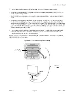
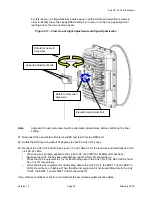
Perform Steps 42 through 49 on the local radio. Then, repeat these steps for the remote radio. See
Figure 2.17.
42 Remove the cap from the BNC connector of the remote radio. Attach the hand-held voltmeter and
BNC test lead to the test point.
43 Fine Azimuth Alignment -- Rotate the Link CX-24 mounting bracket on the pole until the proper
azimuth alignment is achieved. It is advised that, in order to ensure the true maximum, you should
adjust through the maximum RSSI reading until the reading clearly drops and continues to drop to
lower level side-lobes. Adjust back until the maximum is again attained. Expected voltage is more
than +1 VDC. The adjustment should be slowly tuned through the peak, and reset at the absolute
maximum before tightening.
44 Fine Elevation Alignment -- Rotate the Link CX-24 mounting bracket until the proper elevation
alignment is achieved. It is advised that, in order to ensure the true maximum, you should adjust
through the maximum RSSI reading until the reading clearly drops and continues to drop to lower
level side-lobes. Adjust back until the maximum is again attained. Expected voltage is more than +1
VDC. The adjustment should be slowly tuned through the peak, and reset at the absolute maximum
before tightening the bolts.
45 Tighten the two Azimuth adjustment bolts while observing the RSSI reading to ensure the azimuth
alignment does not change while tightening. Torque the two M8 galvanized hex bolts to 24 N-m
(17.7 lb-ft).
46 Tighten the Elevation adjustment bolt while observing the RSSI reading to ensure the elevation
alignment does not change while tightening. Torque the M8 galvanized hex bolt to 24 N-m (17.7 lb-ft).
CAUTION:
It is possible to obtain a false peak RSSI reading from the signal of a side-lobe. Up to three
different side-lobes on either side of the main lobe may give false peak alignment readings.
Содержание Link CX-24
Страница 1: ...Version 1 0 February 2004 MNL 500224 001...

