Link CX-24 User’s Manual
Version 1.0
Page 20
February 2004
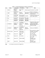
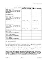
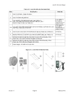
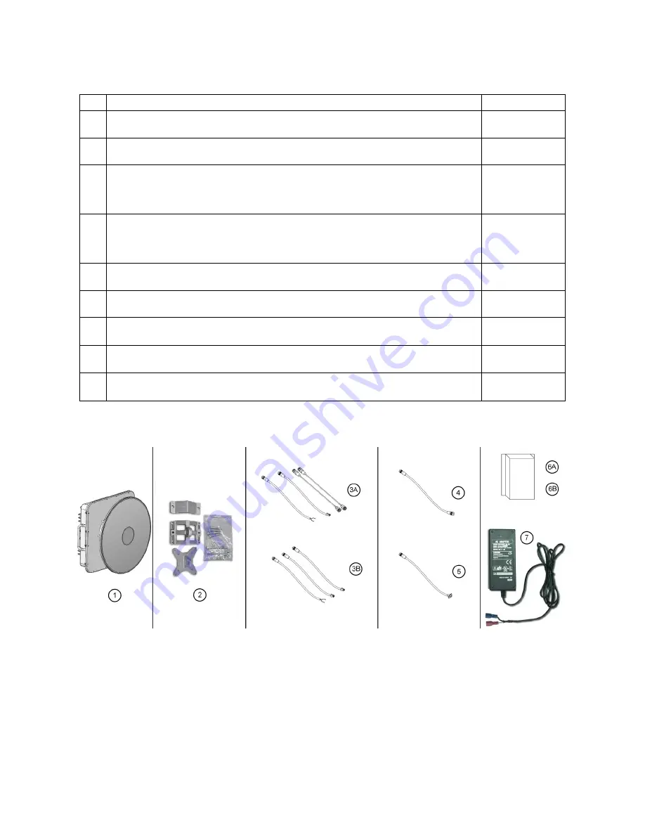
Table 2.3 – Link CX-24 Radio Orderable Parts
Item Description
Remarks
1 Link CX-24 Radio, Integral Antenna
2 Link CX-24 Mounting Bracket
3A
Two each DS-3 Payload Data Cables (see Table A.1),
One 10/100 Ethernet Control Cable (see Table A.2), and
One DC Power Cable (see Table A.3)
All available in
82 ft (25 m),
164 ft (50 m), or
328 ft (100 m)
3B
Two each 10/100 Ethernet Payload and Control Cables (see Table A.2), and
One Power Cable (see Table A.3)
All available in
82 ft (25 m),
164 ft (50 m), or
328 ft (100 m)
4 Link CX-24 to-Link CX-24 10/100 Ethernet Crossover Cable (see Table A.4)
20 ft (6 m)
5 Optional RS-232 CLI Craft PC 4-pin Circular-to-DB9 Cable (see Table A.6)
20 ft (6 m)
6A
Optional Transtector Lightning Arrestor Kit used at the cable entry to the
Power, DS-3 and 10/100 Ethernet Equipment Structure
6B
Optional Transtector Lightning Arrestor Kit used at the cable entry to the
Power and 10/100 Ethernet Equipment Structure
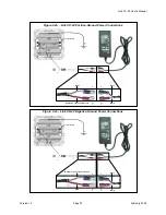
7 Power Supply, 110/220 VAC to 48 VDC
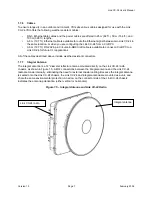
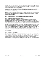
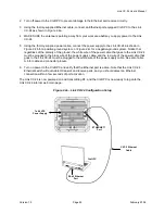
Figure 2.3 – Link CX-24 Orderable Parts
Содержание Link CX-24
Страница 1: ...Version 1 0 February 2004 MNL 500224 001...

