Link CX-24 User’s Manual
Version 1.0
Page 29
February 2004
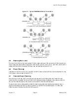
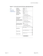
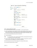
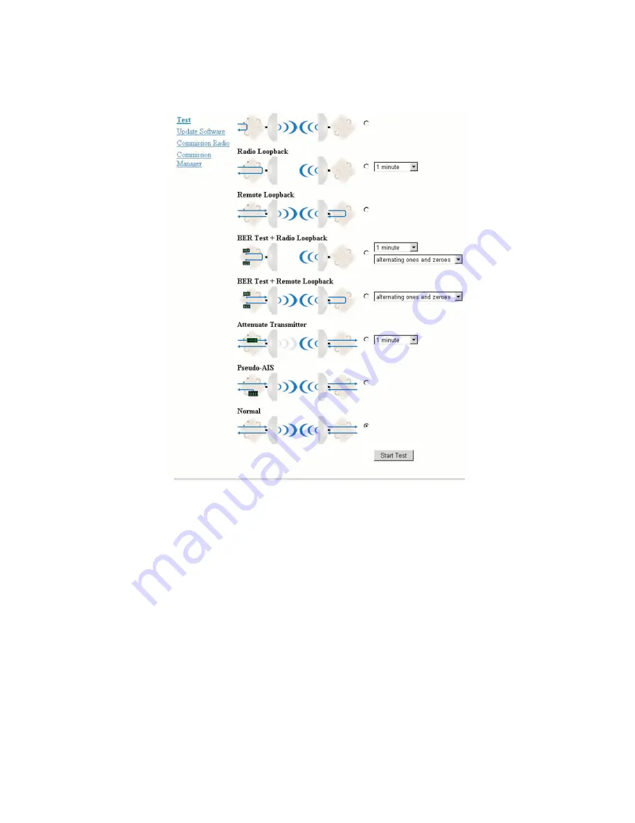
Figure 2.11 – Typical Link CX-24 DS-3 Test Web Page
2.10.4 Testing an Ethernet Link CX-24
21 Connect an external Ethernet device to the ETHERNET 1 or 2 port on the Link CX-24.
22 Use the external Ethernet device to Ping the Link CX-24 at the local Ethernet address configured in
Step 12. Verify that the Link CX-24 responds to the Ping. When the Ping test is complete, the Link
CX-24 has been configured, and the internal Ethernet circuitry of the Link CX-24 has been tested.
23 Disconnect the external Ethernet device from the Link CX-24.
24 Continue with Step 25.
Note:
Do not stand within 2 m (79 in.) of the front of the antenna for prolonged periods during Link
CX-24 operation to avoid harmful RF radiation.
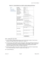
25 On the Commission Radio page, set the Tx Attenuation to disabled. This causes the Link CX-24 to
transmit at the level set by the Maximum Transmit Power parameter.
26 Disconnect power from the Link CX-24 to prepare it for mounting in its final location.
27 Disconnect the Craft PC from the Link CX-24.
Содержание Link CX-24
Страница 1: ...Version 1 0 February 2004 MNL 500224 001...

