background image


Link CX-24 User’s Manual 

Version 1.0 

Page 12 

February 2004 

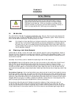
Safety Warning


This antenna/transmitter device must be fixed-mounted on outdoor 
permanent structures with a separation distance of at least 2 meters 
(6.56 feet) from all persons.  Users and installers must adhere to the 
antenna installation instructions and transmitter operating conditions in 
order to comply with the FCC’s RF exposure requirements. 

Section 2   


Installation 


2.1 Introduction 

The Link CX-24 is intended for professional installation only. However, this manual is also designed for 
personnel who plan, operate and administer the Link CX-24 communication system. Please review the 
entire manual before powering up or deploying any Link CX-24. 
 

Note:


It is strongly recommended that you configure and test the units prior to deploying them in the 
field. Set up a “mini-network” that resembles your actual configuration as close as possible. 
By using such a mock-up, troubleshooting potential problems will be much easier than if you 
already installed the equipment in the field. Read through this entire Section 2 to understand 
how to install the hardware. 

2.2 

Planning a Link CX-24 Network 

As described in Section 1.8, the Link CX-24 can be used to support a number of applications. However, 
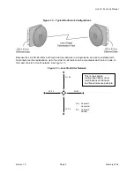
the most common configuration is a point-to-point network. Point-to-point configurations (Figure 1.1) are 
easiest to plan and implement, as the radio links merely transmit industry-standard formatted data from 
one location to another. 
 
Generally, the common points to consider when planning a Link CX-24 network are: 
 

Line of Sight: 

Unlike some frequency bands, the Link CX-24 radios must be within line of sight of each 

other. That is, the far-end antenna must be visible from the near-end antenna. If there are trees, 
buildings, mountains, or other obstructions between the two antennas, the Link CX-24s on each end of 
the radio link will be unable to communicate with each other. Make sure the Link CX-24 radios used in 
each radio link are within line of sight of each other. Refer also to the Fresnel Zone Clearance section that 
follows. 
 

Fresnel Zone Clearance: 

There must be sufficient open space around the direct line of sight to minimize 

interference with the radio beam. At a minimum, 60% of the first Fresnel zone of the path should be clear. 
Even with clear line-of-sight, objects still may be near enough to the transmission path to cause problems. 
Obviously, objects that stand directly in the transmission path obstruct the beam, causing a drop in signal 
strength at the receiving end; in addition, objects and reflective surfaces that are in near proximity to the 
path can cause signal interference and attenuation of the received signal. 
 
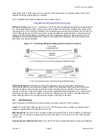
Fresnel zones define the amount of clearance required for obstacles. These zones are series of 
concentric ellipsoid surfaces that surround the straight-line path between the two antennas. The first 
Fresnel zone is defined as the surface containing every point for which the distance from the transmitter 
to any reflection point on the surface and then on to the receiver is one-half wavelength longer than the 


CAUTION 

Содержание Link CX-24

Страница 1: ...Version 1 0 February 2004 MNL 500224 001...

Страница 2: ...ghts to copy the software on any medium except as specifically allowed in the license or nondisclosure agreement The Link CX 24 product line is covered by one or more of the following United States Pa...

Страница 3: ...on or RF antenna as eyes are particularly vulnerable to radiation Do not disconnect RF coaxial connectors open microwave units or break down any microwave screening while the radio equipment is operat...

Страница 4: ...Configuration 21 2 11 Mounting the Link CX 24 30 2 13 Completing the Link CX 24 Installation 33 2 14 Aligning the Antenna 35 2 15 Acceptance Testing 37 2 16 Final Link CX 24 Configuration 40 2 17 Upda...

Страница 5: ...nd Level Surfaces 13 Figure 2 2 Typical EMS NMS Ethernet Connections 15 Figure 2 3 Link CX 24 Orderable Parts 20 Figure 2 4a Link CX 24 Configuration Setup 22 Figure 2 4b Link CX 24 Positive Ground Po...

Страница 6: ...Web Page 41 Figure 2 19 Typical Ethernet Update Software Web Page 41 Figure C 1 Link CX 24 Login Window all models 52 Figure C 2 Link CX 24 DS 3 Monitor Web Page 53 Figure C 3 Link CX 24 DS 3 Commissi...

Страница 7: ...le 2 5 Physical Installation Checklist 37 Table 2 6 Electrical Connection Checklist 38 Table 2 7 DS 3 Internal Circuit and Radio Link Checklist 39 Table 2 8 Ethernet Internal Circuit and Radio Link Ch...

Страница 8: ...on Compliance Other countries have varying RF licensing and operating requirements and it is imperative that operators and professional installers ensure that the Link CX 24 is configured and installe...

Страница 9: ...ers CAPs and Competitive Local Exchange Carriers CLECs 1 5 System Overview Each Link CX 24 consists of a Link CX 24 radio with integral antenna as shown in Figure 1 2 along with external power and dat...

Страница 10: ...can be installed with horizontal or vertical polarization up to four Link CX 24 radios can be mounted at each hub or node to form part of a star or mesh network See Figure 1 3 Figure 1 3 Link CX 24 S...

Страница 11: ...d backup software versions contained in Link CX 24 memory operator selectable 1 7 Link CX 24 Basic Structure 1 7 1 Radio Links Each radio link includes two Link CX 24 terminals Each terminal consists...

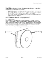
Страница 12: ...he single bracket mounts one Link CX 24 The bracket is designed to provide rugged mounting for the Link CX 24 while allowing fine adjustment for antenna alignment 1 7 5 Interface Connectors and Indica...

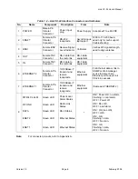
Страница 13: ...e radio link DS 3 data equipment 5 IN Female TNC Connector DS 3 data to the radio link DS 3 data equipment 6 ETHERNET 2 Female 4 Pin Circular Connector 10 100Base T transmit and receive receptacle Eth...

Страница 14: ...Craft PC to a Link CX 24 for future CLI applications All of the cables described above include weather resistant connectors 1 7 7 Integral Antenna The integral antenna is a 12 diameter reflector ante...

Страница 15: ...le via the Link CX 24 built in web server or via SNMP polls Five LEDs that provide visual alarm status They verify proper operation of the Ethernet ports DS3 ports and radio link and indicate proper p...

Страница 16: ...ing the ETHERNET 1 and ETHERNET 2 ports between Link CX 24 radios using straight pinned or crossover Ethernet cables 1 7 12 Web Based GUI Access Security Access to the Web based GUI graphical user int...

Страница 17: ...supported on the Link CX 24 Ethernet versions as any loop back could result in an immediate data storm Instead YDI recommends that customers use external equipment to Ping use Packet Internet Groper...

Страница 18: ...thout extensive telecommunications infrastructure or in areas where the cost of local access is high installing and maintaining a Link CX 24 radio network can be very cost effective Typical users of p...

Страница 19: ...ata from one location to another Generally the common points to consider when planning a Link CX 24 network are Line of Sight Unlike some frequency bands the Link CX 24 radios must be within line of s...

Страница 20: ...2 1 Preventing Multi path Fading from Ground Level Surfaces External Interference Because the Link CX 24 operates in an unlicensed band YDI strongly recommends that you use a spectrum analyzer at both...

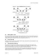
Страница 21: ...d Figure 2 2 shows some common arrangements for the EMS and or NMS Ethernet links The cable run from the Ethernet switch or router to the Link CX 24 must be 100 m 328 ft or less and can be straight th...

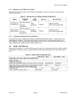
Страница 22: ...and 100 m 328 ft power cables with the correct connectors for Link CX 24 power as described in Section 1 7 6 2 7 Transmit Power Planning The Link CX 24 normally uses a manually set output power level...

Страница 23: ...here are other receivers beyond the remote Link CX 24 terminal for instance in a mesh network In this case the professional installer must use the free space calculation to determine the actual Maximu...

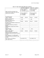
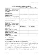
Страница 24: ...n 2 7 Enabled Disabled Enabled Disabled IP Address must be different obtain from IP network planner _ _ _ _ _ _ _ _ _ _ _ _ _ _ _ _ _ _ _ _ _ _ _ _ Subnet Mask obtain from IP network planner _ _ _ _ _...

Страница 25: ..._ _ System Name optional up to 255 ASCII characters System Contact Information optional up to 255 ASCII characters System Location optional up to 255 ASCII characters 2 9 Before Installing 2 9 1 Gene...

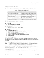
Страница 26: ...shipped with the Link CX 24 User s Manual and mounting hardware Unpack each box and examine the exterior of each unit for any visible damage If visible damage is detected immediately contact your sal...

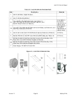
Страница 27: ...d and Control Cables see Table A 2 and One Power Cable see Table A 3 All available in 82 ft 25 m 164 ft 50 m or 328 ft 100 m 4 Link CX 24 to Link CX 24 10 100 Ethernet Crossover Cable see Table A 4 20...

Страница 28: ...ft PC command line interface Future option Standoffs and or tie wraps or similar for fastening cables Vinyl or equivalent electrical tape Butyl rubber amalgamating connector sealing tape Customer supp...

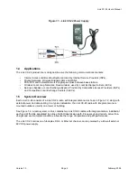
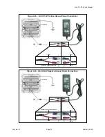
Страница 29: ...nd the white wire of the power cable that goes to the Link CX 24 must be plugged to the black wire of the power supply cable and the red wire of the power cable that goes to the Link CX 24 must be plu...

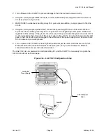
Страница 30: ...ruary 2004 Figure 2 4b Link CX 24 Positive Ground Power Connections Black White To Craft PC White Red Wire is Connected to Ground Figure 2 4c Link CX 24 Negative Ground Power Connections White Wire is...

Страница 31: ...wser If the web browser Ethernet address has been changed use the replacement Ethernet address instead of http 10 0 0 x 9 If the Link CX 24 has not been configured for a login and password continue wi...

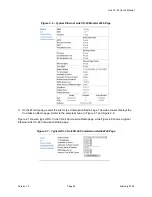
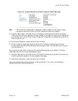
Страница 32: ...e link for the Commission Radio page The web browser displays the Commission Radio page similar to the samples shown in Figure 2 7 and Figure 2 8 Figure 2 7 shows a typical DS 3 Link CX 24 Commission...

Страница 33: ...wer Control for now 13 Click Submit Changes to upload changes to the Link CX 24 14 On the Commission Radio page select the link for the Commission Interfaces page The web browser displays the Commissi...

Страница 34: ...Link CX 24 User s Manual Version 1 0 Page 27 February 2004 Figure 2 9 Typical DS 3 Link CX 24 Commission Manager Web Page...

Страница 35: ...est page select the BERT Radio Loop back test and select One Minute Select Start Test to verify the internal Link CX 24 circuitry before installation When the BERT Radio Loop back test is complete the...

Страница 36: ...nk CX 24 has been configured and the internal Ethernet circuitry of the Link CX 24 has been tested 23 Disconnect the external Ethernet device from the Link CX 24 24 Continue with Step 25 Note Do not s...

Страница 37: ...it Figure 2 12 Link CX 24 Mounting Components 28 Select the Link CX 24 Polarization Since the Link CX 24 is equipped with an integral antenna how the adapter bracket X is mounted to the unit determine...

Страница 38: ...ting studs on the back of the unit with the adaptor bracket holes and securing to the unit using four M5 nuts flat washers and lock washers as shown in Figure 2 14 Tighten hardware four places Torque...

Страница 39: ...24 to a 1 75 diameter pole Do not tighten at this stage The pole mounting bracket A will accept pole diameters between 1 75 to 3 OD The Link CX 24 unit can be mounted to larger pole diameters by disca...

Страница 40: ...thernet equipment Leave a minimum of 38 cm 15 inches of service loop in the cables where they attach to the lightning arrestor Avoid tight bends during cable routing and fastening 33 Connect the power...

Страница 41: ...24 the ENET 1 and or ENET 2 LEDs should be on or flashing When the Ethernet equipment is not transmitting data to the Link CX 24 the ENET 1 and or ENET 2 LEDs should be off or flashing as local data i...

Страница 42: ...nd held voltmeter and BNC test lead to the test point 43 Fine Azimuth Alignment Rotate the Link CX 24 mounting bracket on the pole until the proper azimuth alignment is achieved It is advised that in...

Страница 43: ...ink CX 24 LEDs See Figure 1 3 and Table 4 2 for the locations and descriptions of the Link CX 24 LEDs When power is properly applied to the Link CX 24 the PWR LCL ALARM LED will be on Because the radi...

Страница 44: ...Verified Inspector Date Is the mounting pipe securely connected to the mounting structure Is the Link CX 24 securely connected to the mounting pipe Is the lightning protection above the Link CX 24 pr...

Отзывы: