Link CX-24 User’s Manual
Version 1.0
Page 36
February 2004
For this reason, it is important that a wide sweep in both azimuth and elevation is made in
order to identify these false peak RSSI readings so to zero in on the true peak alignment
reading due to the main antenna beam.
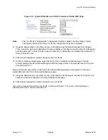
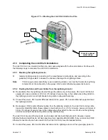
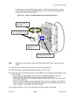
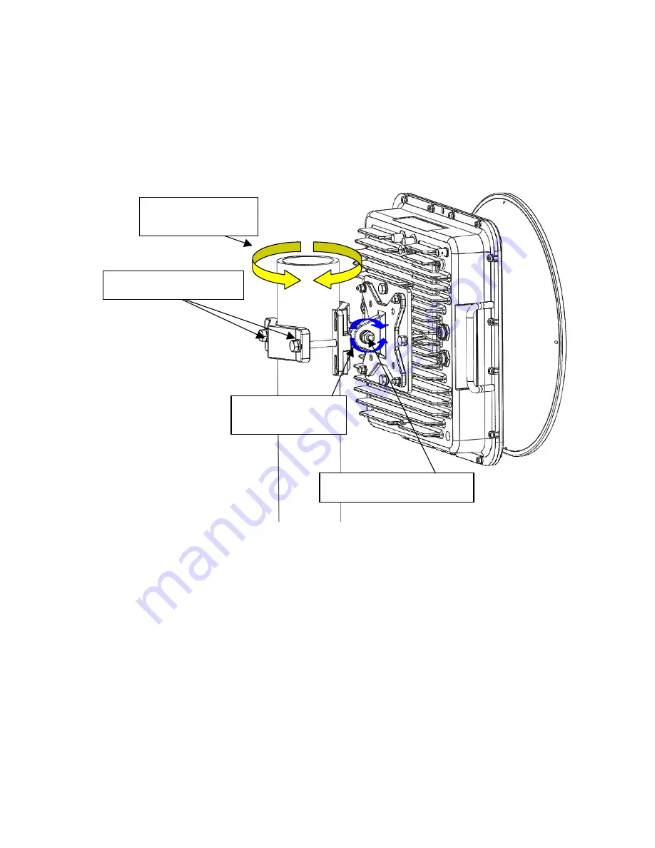
Figure 2.17 – Final Line-of-Sight Adjustment and Signal Optimization
Note:
Alignment for each antenna should be alternated at least twice before confirming the final
setting.
47 Disconnect the hand-held voltmeter and BNC test lead from the RSSI port.
48 Rotate the RSSI port cap about 90 degrees to seal the Link CX-24 case.
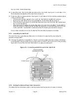
49 Recheck the Link CX-24 LEDs. See Figure 1.3 and Table 4.2 for the locations and descriptions of the
Link CX-24 LEDs.
•
When power is properly applied to the Link CX-24, the PWR/LCL ALARM LED will be on.
•
Because the radio link has been established, the RF LINK LED should be on.
•
When the DS-3 equipment is or is not transmitting data to the Link CX-24, the DATA LED should
be on or off, respectively.
•
When the Ethernet equipment is transmitting data to the Link CX-24, the ENET 1 and/or ENET 2
LEDs should be on or flashing. When the Ethernet equipment is not transmitting data to the Link
CX-24, the ENET 1 and/or ENET 2 LEDs should be off.
If any of these conditions is not true, troubleshoot the associated equipment and cables.
Rotate for azimuth
alignment
Rotate for elevation
alignment
Azimuth adjustment bolts
Elevation adjustment bolt
Содержание Link CX-24
Страница 1: ...Version 1 0 February 2004 MNL 500224 001...

