
Link CX-24 User’s Manual
Version 1.0
Page 22
February 2004
2 Turn off power to the Craft PC to prevent damage to the Ethernet port receive circuitry.
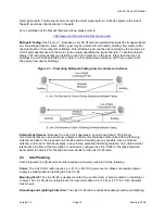
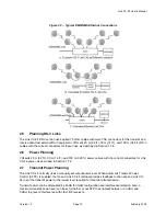
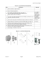
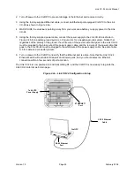
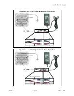
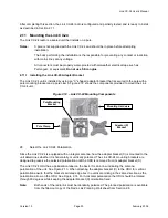
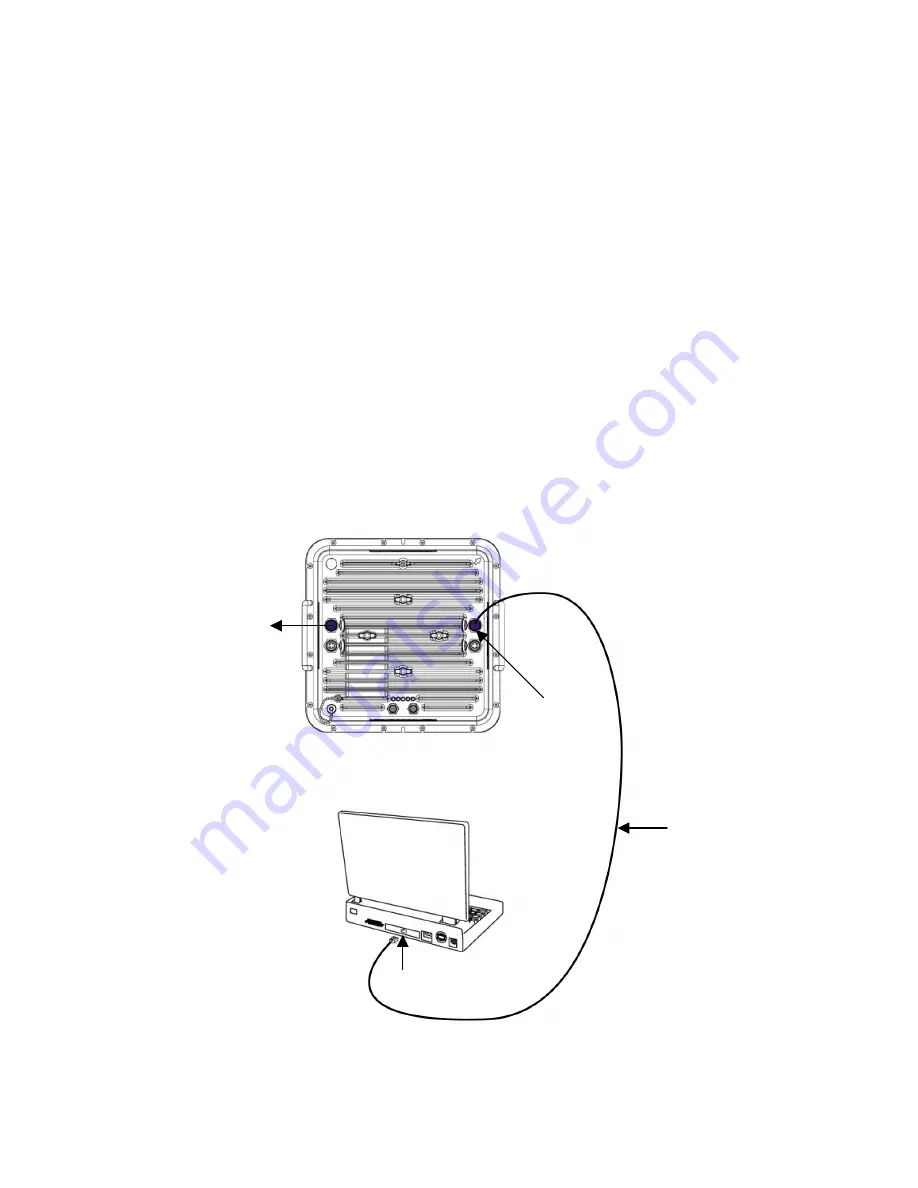
3 Using the factory-supplied Ethernet cable, connect an Ethernet-port equipped Craft PC to the Link
CX-24 as shown in Figure 2.4a.
4 MAKE SURE the antenna is pointing away from your work area before you apply power to the Link
CX-24.
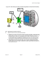
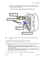
5 Using the factory-supplied power cable, connect the power supply to the Link CX-24 as shown in
Figure 2.4b for a positive-ground system, or Figure 2.4c for a negative-ground system. Notice that
regardless of the polarity of the ground, the white wire of the power cable that goes to the Link CX-24
must be plugged to the black wire of the power supply cable, and the red wire of the power cable that
goes to the Link CX-24 must be plugged to the white wire of the power supply cable. See also Table
A.6 for cable and connector pinouts.
6 Turn on power to the Craft PC and verify that the Ethernet port is active. Note that the Link CX-24
Ethernet switch will auto-detect transmit and receive pairs, and you should detect an Ethernet
connection within a few seconds of port activation.
The Link CX-24 is now powered on and transmitting RF, and the Craft PC is now ready to log onto the
Link CX-24 internal web main page.
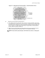
Figure 2.4a – Link CX-24 Configuration Setup
CAT-5 Ethernet
Cable
Craft PC
RJ-45 Ethernet
Port
ETHERNET 1
Port
To 48 VDC
Power Supply
Содержание Link CX-24
Страница 1: ...Version 1 0 February 2004 MNL 500224 001...