


222
CHAPTER
ELEVEN
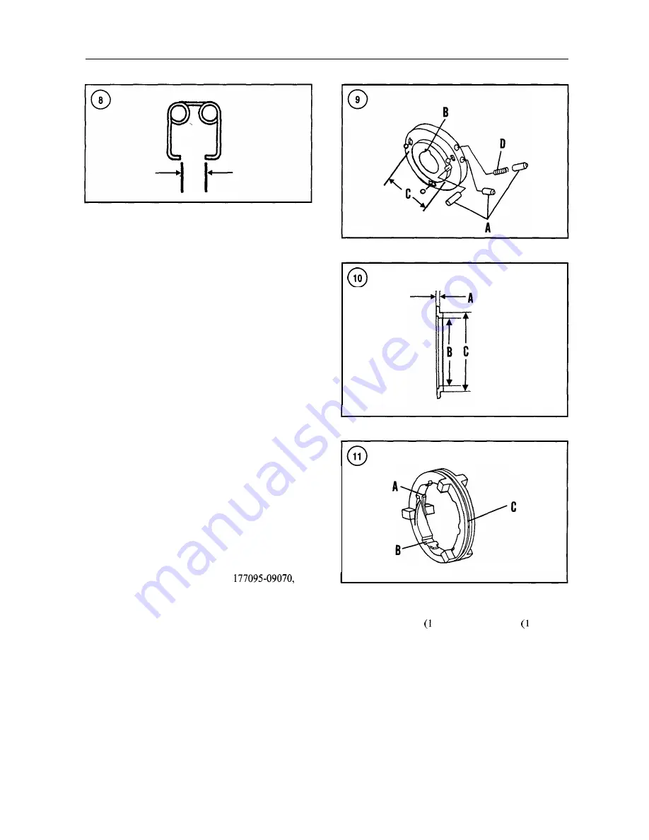
16. Measure the return spring end gap (Figure
8) and
compare the result with the specification in Table 3.
17. Check the driving plate ball grooves (Figure 9),
detent pin bores, detent pins (A) and keyway (B) for any
noticeable wear.
18. Measure the driving plate hub outer diameter (C, Fig-
ure 9) and compare it with the specification in Table 3.
19. Measure detent pin spring
(D, Figure 9) free length
and compare it with the specification in Table 3.
20. Measure the plate spring retainer thickness (A, Fig-
ure 10) and compare the result with the specification in
Table 3. Measure the plate spring inside diameter (B) and
compare with the specification in Table
3. Measure the
plate spring shoulder diameter (C) and compare the result
with the specification in Table 3.
2 1. Measure the free width of the Belleville springs and
compare it with the specification in Table 3.
22. Inspect the shift ring pressure grooves (A, Figure 11)
and pin contact grooves (B) for any signs of excessive
wear. Measure the width of the circumferential groove (C)
and compare the result with the specification in Table 3.
Reassembly
1. Install the Belleville springs on the forward gear so the
concave sides face each other as shown in Figure 12. Po-
sition the retainer (12, Figure 3) over the Belleville
springs and slide the snap ring onto the spline of the for-
ward gear. Using Yanmar special tool
or a
suitable equivalent tool, compress the forward gear as-
sembly in a vise and engage the snap ring in the groove
around the forward gear splines.
2. Refer to Step 1 and assemble the reverse gear,
Belleville springs, retainer and snap ring.
3.
To determine the correct thickness of shims (16 and 26,
Figure 3), install the inner bearing race and spacer in their
respective gears. Measure the depth (A, Figure 13) of the
bearing race from the end of the gear as shown in Figure
13. Install shims equal to the depth.
4. Alternately install four friction plates (14, Figure 3)
and three steel plates 5) on the forward gear 0) splines
starting with a friction plate.
5. Refer to Step 4 and assemble the reverse gear, steel
plates and friction plates.
6 .
Using a suitable bearing driver, install the output shaft
front bearing onto the shaft. Be sure the bearing inner race
contacts the collar on the end of the output shaft.
Содержание 1GM10
Страница 1: ...YANMAR DIESEL INBOARD SHOP MANUAL ONE TWO 8 THREE CYLINDER ENGINES...
Страница 6: ......
Страница 7: ......
Страница 9: ......
Страница 10: ......
Страница 11: ......
Страница 12: ......
Страница 13: ......
Страница 16: ......
Страница 17: ......
Страница 18: ......
Страница 19: ......
Страница 20: ......
Страница 21: ......
Страница 22: ......
Страница 23: ......
Страница 24: ......
Страница 25: ......
Страница 26: ......
Страница 27: ......
Страница 28: ...GENERAL INFORMATION 21 Bearing Blocks Press Shaft arm Bearing Spacer Press k 4 bed...
Страница 36: ...30 CHAPTER TWO CHARGING SYSTEM TYPICAL Battery switch...
Страница 39: ......
Страница 44: ...38 CHAPTER TWO LUBRICATION SYSTEM 2GM AND 2GM20 MODELS...
Страница 45: ...TROUBLESHOOTING 39 LUBRICATION SYSTEM 3GM 3GM30 3HM AND 3HM35 MODELS 3HM AND 3HM35 MODELS Filter...
Страница 46: ......
Страница 50: ......
Страница 52: ......
Страница 54: ......
Страница 55: ......
Страница 57: ......
Страница 58: ......
Страница 64: ......
Страница 66: ......
Страница 70: ......
Страница 71: ......
Страница 77: ......
Страница 78: ......
Страница 79: ......
Страница 80: ......
Страница 81: ......
Страница 82: ......
Страница 89: ......
Страница 90: ......
Страница 91: ......
Страница 92: ......
Страница 93: ......
Страница 94: ......
Страница 95: ......
Страница 96: ......
Страница 97: ......
Страница 98: ......
Страница 99: ......
Страница 100: ......
Страница 101: ......
Страница 102: ......
Страница 112: ...106 CHAPTER SIX...
Страница 114: ......
Страница 123: ......
Страница 124: ......
Страница 125: ......
Страница 126: ......
Страница 129: ......
Страница 130: ......
Страница 131: ......
Страница 133: ......
Страница 134: ......
Страница 135: ......
Страница 136: ......
Страница 145: ...FUEL INJECTION AND GOVERNOR SYSTEMS 139 FUEL INJECTION SYSTEM Fuel tank hose fuel pipe...
Страница 148: ......
Страница 149: ......
Страница 150: ......
Страница 151: ......
Страница 152: ......
Страница 153: ......
Страница 154: ......
Страница 155: ......
Страница 156: ......
Страница 157: ......
Страница 158: ......
Страница 165: ......
Страница 166: ...160 CHAPTER EIGHT SEAWATER COOLING SYSTEM 1GM AND 1GMlO Mixing elbow Rubber hose I Drain Seacock except 1GM1OC...
Страница 167: ...COOLING SYSTEM 161 SEAWATER COOLING SYSTEM 2GM AND 2GM20 U type mixing elbow Rubber hose Seacock except 2GM20C...
Страница 170: ...164 CHAPTER EIGHT CLOSED COOLING SYSTEM TYPICAL rnlxlng elbow Joint...
Страница 172: ......
Страница 174: ......
Страница 175: ......
Страница 176: ......
Страница 177: ......
Страница 184: ......
Страница 190: ......
Страница 196: ......
Страница 197: ......
Страница 201: ......
Страница 202: ......
Страница 204: ......
Страница 205: ......
Страница 208: ......
Страница 209: ......
Страница 219: ......
Страница 224: ...218 CHAPTER ELEVEN...
Страница 231: ......
Страница 235: ......


