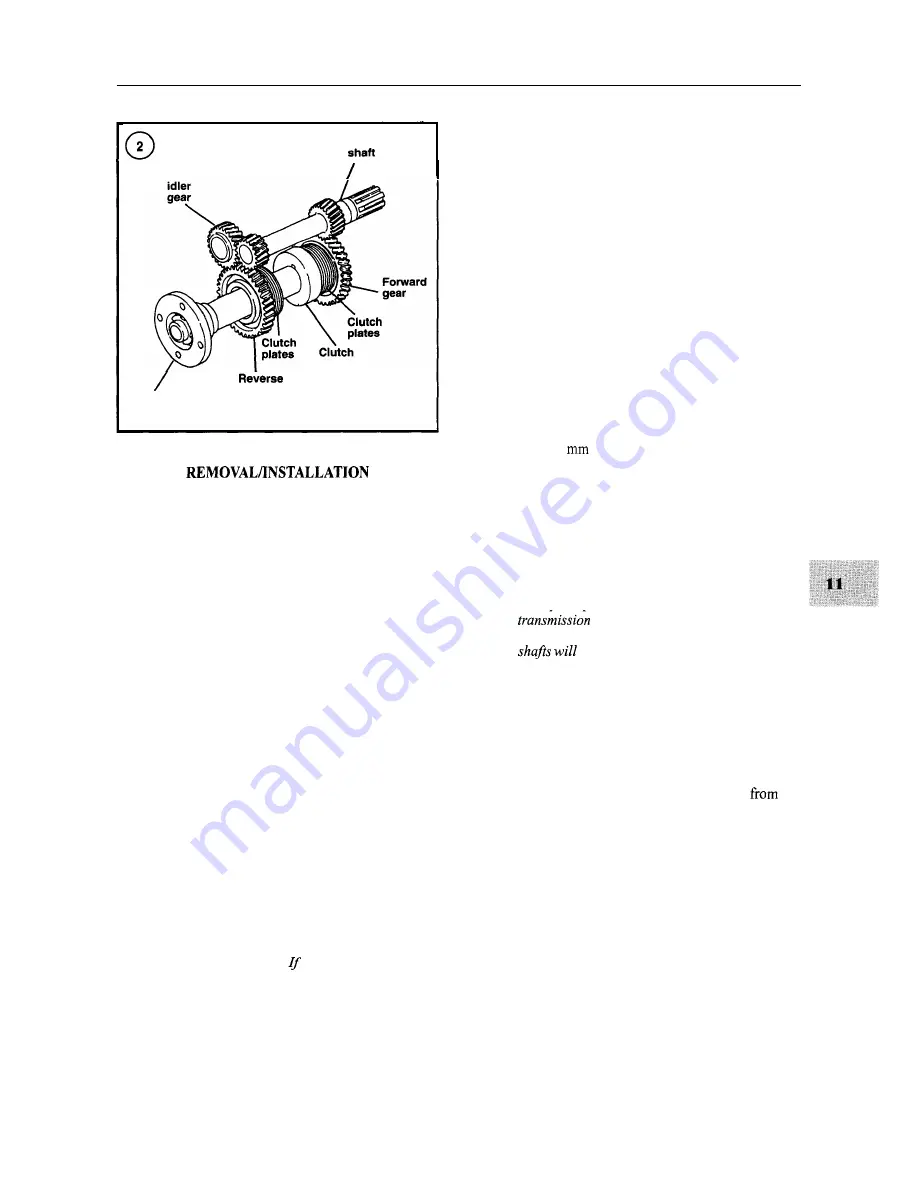
TRANSMISSION-KBW SERIES
217
Input
Reverse
gear
Coupling flange
The following procedure addresses units that are acces-
sible. In some cases, it may be necessary to remove the en-
gine and transmission as a unit before removing the
transmission from the engine. Refer to Chapter Six if en-
gine removal is necessary.
1. If not previously disconnected, disconnect the remote
control cable from the transmission shift lever.
2. If not previously disconnected, disconnect the drive
coupling from the transmission drive flange.
3. Remove the bolts that secure the transmission to the
engine bellhousing.
4. Remove the transmission from the engine.
5. Reinstall the transmission by reversing the removal
procedure. Make sure
to align the splines on the transmis-
sion input shaft and the drive disc during installation.
Tighten the transmission retaining bolts to the torque
specified in Table 2.
OVERHAUL
Refer to Figure 3.
NOTE
Overhaul of the
KB
W transmission requires
special tools, which can be obtained from
Yanmar or fabricated.
the special tools
are not available, have a Yanmar dealership
overhaul the transmission.
Disassembly
1.
Remove the drain plug and drain the transmission oil.
2. Position the transmission in a vise with soft jaws so the
input shaft is held by the vise jaws.
3. The output flange retaining nut is staked. Use a chisel
to cut away the staked portion so the nut will rotate.
4. Install a tool that will prevent rotation of the output
flange.
5. Unscrew the output flange retaining nut.
6. Remove the oil dipstick.
7. Make match marks on the shifter cover and the trans-
mission case so the shifter can be installed in its original
position.
8. Remove the shifter retaining bolts and remove the
shifter assembly.
9. Remove the transmission from the vise.
10. Using an 8
Allen wrench, remove the shift bar re-
taining plug (68, Figure 3) in the rear of the case.
11. Install a 10 mm bolt into the end of the shift bar, then
pull the shift bar (58, Figure 3) out of the case while also
removing the shift fork (57).
12. Remove the transmission mounting flange retaining
bolts.
NOTE
In Step 13, position the transmission so the
input shaft is up when remov-
ing the mountingflange so the transmission
not fall out.
13. Tap on the mounting flange using a soft-faced ham-
mer to dislodge the flange. Position the transmission with
the input shaft up, then remove the flange from the trans-
mission case.
14. Remove the output shaft assembly from the transmis-
sion case and set aside for disassembly.
15. Remove the intermediate shaft assembly
the
transmission case and set aside for disassembly.
16. Remove the input shaft assembly from the transmis-
sion case and set aside for disassembly.
17. Using a large screwdriver, pry out the oil seal in the
transmission case. Be careful not to damage the case or
the adjacent bearing race.
18. Using a large screwdriver, pry out the oil seal in the
transmission mounting flange. Be careful not to damage
the case or the adjacent bearing race.
19. If inspection indicates additional disassembly is nec-
essary, refer to the following sections.
Содержание 1GM10
Страница 1: ...YANMAR DIESEL INBOARD SHOP MANUAL ONE TWO 8 THREE CYLINDER ENGINES...
Страница 6: ......
Страница 7: ......
Страница 9: ......
Страница 10: ......
Страница 11: ......
Страница 12: ......
Страница 13: ......
Страница 16: ......
Страница 17: ......
Страница 18: ......
Страница 19: ......
Страница 20: ......
Страница 21: ......
Страница 22: ......
Страница 23: ......
Страница 24: ......
Страница 25: ......
Страница 26: ......
Страница 27: ......
Страница 28: ...GENERAL INFORMATION 21 Bearing Blocks Press Shaft arm Bearing Spacer Press k 4 bed...
Страница 36: ...30 CHAPTER TWO CHARGING SYSTEM TYPICAL Battery switch...
Страница 39: ......
Страница 44: ...38 CHAPTER TWO LUBRICATION SYSTEM 2GM AND 2GM20 MODELS...
Страница 45: ...TROUBLESHOOTING 39 LUBRICATION SYSTEM 3GM 3GM30 3HM AND 3HM35 MODELS 3HM AND 3HM35 MODELS Filter...
Страница 46: ......
Страница 50: ......
Страница 52: ......
Страница 54: ......
Страница 55: ......
Страница 57: ......
Страница 58: ......
Страница 64: ......
Страница 66: ......
Страница 70: ......
Страница 71: ......
Страница 77: ......
Страница 78: ......
Страница 79: ......
Страница 80: ......
Страница 81: ......
Страница 82: ......
Страница 89: ......
Страница 90: ......
Страница 91: ......
Страница 92: ......
Страница 93: ......
Страница 94: ......
Страница 95: ......
Страница 96: ......
Страница 97: ......
Страница 98: ......
Страница 99: ......
Страница 100: ......
Страница 101: ......
Страница 102: ......
Страница 112: ...106 CHAPTER SIX...
Страница 114: ......
Страница 123: ......
Страница 124: ......
Страница 125: ......
Страница 126: ......
Страница 129: ......
Страница 130: ......
Страница 131: ......
Страница 133: ......
Страница 134: ......
Страница 135: ......
Страница 136: ......
Страница 145: ...FUEL INJECTION AND GOVERNOR SYSTEMS 139 FUEL INJECTION SYSTEM Fuel tank hose fuel pipe...
Страница 148: ......
Страница 149: ......
Страница 150: ......
Страница 151: ......
Страница 152: ......
Страница 153: ......
Страница 154: ......
Страница 155: ......
Страница 156: ......
Страница 157: ......
Страница 158: ......
Страница 165: ......
Страница 166: ...160 CHAPTER EIGHT SEAWATER COOLING SYSTEM 1GM AND 1GMlO Mixing elbow Rubber hose I Drain Seacock except 1GM1OC...
Страница 167: ...COOLING SYSTEM 161 SEAWATER COOLING SYSTEM 2GM AND 2GM20 U type mixing elbow Rubber hose Seacock except 2GM20C...
Страница 170: ...164 CHAPTER EIGHT CLOSED COOLING SYSTEM TYPICAL rnlxlng elbow Joint...
Страница 172: ......
Страница 174: ......
Страница 175: ......
Страница 176: ......
Страница 177: ......
Страница 184: ......
Страница 190: ......
Страница 196: ......
Страница 197: ......
Страница 201: ......
Страница 202: ......
Страница 204: ......
Страница 205: ......
Страница 208: ......
Страница 209: ......
Страница 219: ......
Страница 224: ...218 CHAPTER ELEVEN...
Страница 231: ......
Страница 235: ......


