2-18
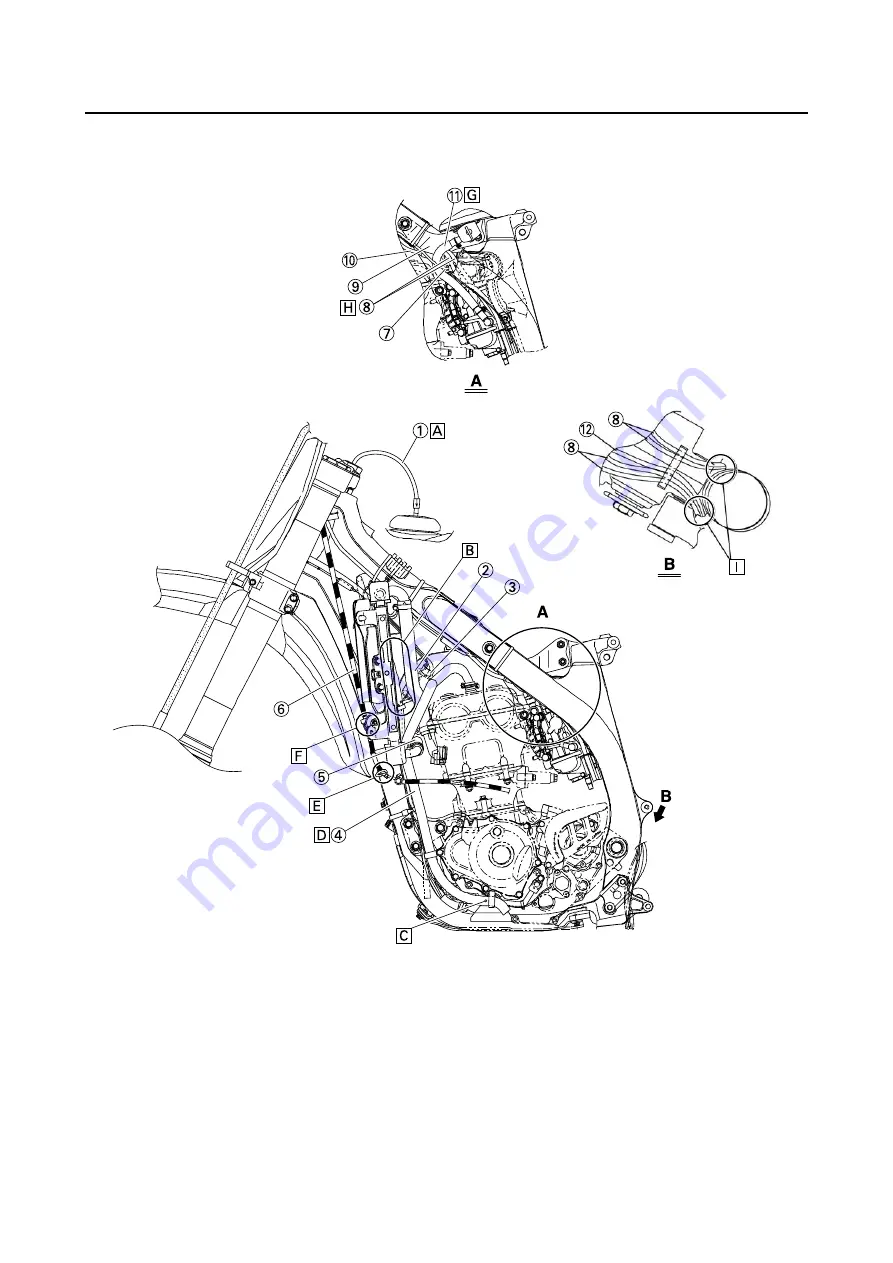
CABLE ROUTING DIAGRAM
CABLE ROUTING DIAGRAM
1.
Fuel tank breather hose
2.
Radiator hose 1
3.
Connector cover
4.
Cylinder head breather hose
5.
Radiator hose 4
6.
Clutch cable
7.
Throttle position sensor lead
8.
Carburetor breather hose
9.
Upper engine bracket
10. Hot starter cable
11. Fuel hose
12. Carburetor overflow hose
A.
Insert the end of the fuel tank
breather hose into the hole in
the steering stem.
B.
Install the connector cover so
that it does not come in between
the radiator hose 1 and radiator.
C.
Aligh the paint mark on the cylin-
der head breather hose with the
front end of the hose guide.
D.
Pass the cylinder head breather
hose on the outside of the radia-
tor hose 1 and then between the
radiator 4 and frame.
E.
Pass the clutch cable through
the cable guide.
Содержание YZ250F X 2008
Страница 2: ......
Страница 3: ...YZ250F X 5XC 28199 34 E0 2008 OWNER S SERVICE MANUAL ...
Страница 4: ......
Страница 39: ...2 17 LUBRICATION DIAGRAMS 1 Crankshaft 2 Oil filter element 3 Oil tank 4 Oil hose A From oil pump ...
Страница 59: ...3 13 ENGINE INTAKE EXHAUST ...
Страница 110: ...4 41 OIL PUMP 15 Rotor housing 1 Order Part name Q ty Remarks ...
Страница 161: ...5 29 STEERING 9 Bearing race 2 Refer to removal section Order Part name Q ty Remarks ...
Страница 170: ...5 38 REAR SHOCK ABSORBER 12 Bearing 2 Refer to removal section Order Part name Q ty Remarks ...
Страница 191: ......
Страница 192: ...PRINTED IN JAPAN E PRINTED ON RECYCLED PAPER YAMAHA MOTOR CO LTD 2500 SHINGAI IWATA SHIZUOKA JAPAN ...


