2-23
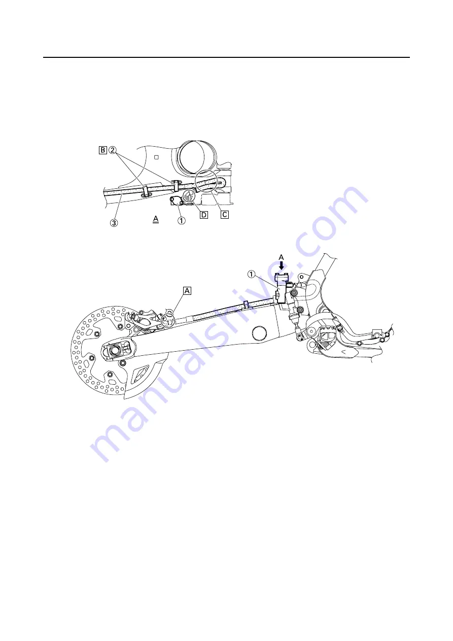
CABLE ROUTING DIAGRAM
1.
Brake master cylinder
2.
Brake hose holder
3.
Brake hose
A.
Install the brake hose so that its
pipe portion directs as shown
and lightly touches the projec-
tion on the brake caliper.
B.
Pass the brake hose into the
brake hose holders.
C.
If the brake hose contacts the
spring (rear shock absorber),
correct its twist.
D.
Install the brake hose so that its
pipe portion directs as shown
and lightly touches the projec-
tion on the brake master cylin-
der.
Содержание YZ250F X 2008
Страница 2: ......
Страница 3: ...YZ250F X 5XC 28199 34 E0 2008 OWNER S SERVICE MANUAL ...
Страница 4: ......
Страница 39: ...2 17 LUBRICATION DIAGRAMS 1 Crankshaft 2 Oil filter element 3 Oil tank 4 Oil hose A From oil pump ...
Страница 59: ...3 13 ENGINE INTAKE EXHAUST ...
Страница 110: ...4 41 OIL PUMP 15 Rotor housing 1 Order Part name Q ty Remarks ...
Страница 161: ...5 29 STEERING 9 Bearing race 2 Refer to removal section Order Part name Q ty Remarks ...
Страница 170: ...5 38 REAR SHOCK ABSORBER 12 Bearing 2 Refer to removal section Order Part name Q ty Remarks ...
Страница 191: ......
Страница 192: ...PRINTED IN JAPAN E PRINTED ON RECYCLED PAPER YAMAHA MOTOR CO LTD 2500 SHINGAI IWATA SHIZUOKA JAPAN ...


