4-24
VALVES AND VALVE SPRINGS
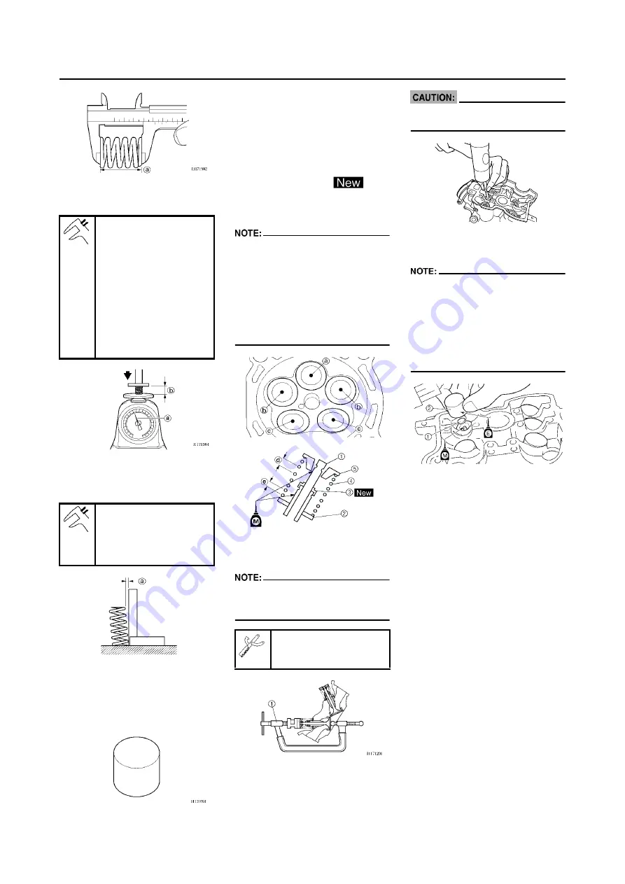
2. Measure:
• Compressed spring force "a"
Out of specification
→
Replace.
b.
Installed length
3. Measure:
• Spring tilt "a"
Out of specification
→
Replace.
CHECKING THE VALVE LIFTERS
1. Inspect:
• Valve lifter
Scratches/damage
→
Replace
both lifters and cylinder head.
INSTALLING THE VALVES
1. Apply:
• Molybdenum disulfide oil
Onto the valve stem and valve
stem seal.
2. Install:
• Valve "1"
• Valve spring seat "2"
• Valve stem seal "3"
• Valve spring "4"
• Valve spring retainer "5"
To cylinder head.
• Make sure that each valve is in-
stalled in its original place, also re-
ferring to the painted color as
follows.
Intake (middle) "a": Orange
Intake (right/left) "b": Green
Exhaust "c": Purple
• Install the valve springs with the
larger pitch "d" facing upward.
e.
Smaller pitch
3. Install:
• Valve cotter
While compressing the valve spring
with a valve spring compressor "1" in-
stall the valve cotters.
4. To secure the valve cotters onto
the valve stem, lightly tap the
valve tip with a piece of wood.
Hitting the valve tip with excessive
force could damage the valve.
5. Install:
• Adjusting pad "1"
• Valve lifter "2"
• Apply the molybdenum disulfide oil
on the valve stem end.
• Apply the engine oil on the valve lift-
ers.
• Valve lifter must turn smoothly
when rotated with a finger.
• Be careful to reinstall valve lifters
and pads in their original place.
Compressed spring
force:
Intake:
99–114 N at 29.13 mm
(9.9–11.4 kg at 29.13
mm, 22.27–25.57 lb at
1.15 in)
Exhaust:
126–144 N at 29.30
mm (12.6–14.4 kg at
29.30 mm, 28.44–
32.41 lb at 1.15 in)
Spring tilt limit:
Intake:
2.5°/1.7 mm (0.067 in)
Exhaust:
2.5°/1.6 mm (0.063 in)
Valve spring compres-
sor:
YM-4019/90890-04019
Содержание YZ250F X 2008
Страница 2: ......
Страница 3: ...YZ250F X 5XC 28199 34 E0 2008 OWNER S SERVICE MANUAL ...
Страница 4: ......
Страница 39: ...2 17 LUBRICATION DIAGRAMS 1 Crankshaft 2 Oil filter element 3 Oil tank 4 Oil hose A From oil pump ...
Страница 59: ...3 13 ENGINE INTAKE EXHAUST ...
Страница 110: ...4 41 OIL PUMP 15 Rotor housing 1 Order Part name Q ty Remarks ...
Страница 161: ...5 29 STEERING 9 Bearing race 2 Refer to removal section Order Part name Q ty Remarks ...
Страница 170: ...5 38 REAR SHOCK ABSORBER 12 Bearing 2 Refer to removal section Order Part name Q ty Remarks ...
Страница 191: ......
Страница 192: ...PRINTED IN JAPAN E PRINTED ON RECYCLED PAPER YAMAHA MOTOR CO LTD 2500 SHINGAI IWATA SHIZUOKA JAPAN ...


