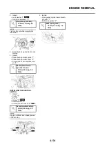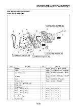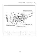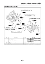
4-59
CRANKCASE AND CRANKSHAFT
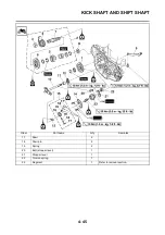
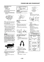
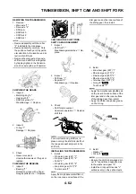
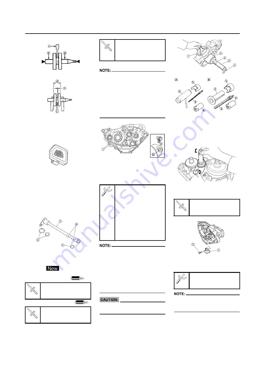
CHECKING THE OIL STRAINER
1. Inspect:
• Oil strainer
Damage
→
Replace.
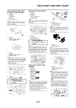
CHECKING THE OIL DELIVERY
PIPE 2
1. Inspect:
• Oil delivery pipe 2 "1"
• O-ring "2"
Damage
→
Replace.
• Oil orifice "a"
Clogged
→
Blow.
INSTALLING THE CRANKCASE
BEARING
1. Install:
• Bearing
• Bearing stopper
• Bolt (bearing stopper)
• Screw (bearing stopper)
• Screw [bearing stopper (crank-
shaft)] "1"
To left and right crankcase.
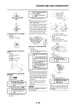
• Install the bearing by pressing its
outer race parallel.
• To prevent the screw [bearing stop-
per (crankshaft)] from becoming
loose, crush the screw head periph-
ery "a" into the concave "b" using a
punch etc. In so doing, take care
not to damage the screwdriver re-
ceiving hole in the screw head.
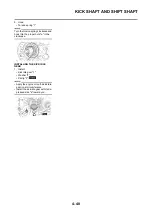
INSTALLING THE CRANKSHAFT
1. Install:
• Crankshaft "1"
Use the crankshaft installing tool
"2", "3", "4" and "5".
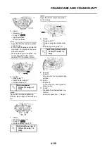
• Hold the connecting rod at top dead
center with one hand while turning
the nut of the installing tool with the
other. Operate the installing tool un-
til the crankshaft bottoms against
the bearing.
• Before installing the crankshaft,
clean the contacting surface of
crankcase.
Do not use a hammer to drive in
the crankshaft.
A.
For USA and CDN
B.
Except for USA and CDN
2. Check:
• Shifter operation
• Transmission operation
Unsmooth operation
→
Repair.
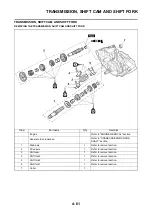
3. Install:
• Oil strainer "1"
• Bolt (oil strainer) "2"
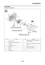
4. Apply:
• Sealant
On the right crankcase "1".
Clean the contacting surface of left
and right crankcase before applying
the sealant.
Bolt (bearing stopper):
10 Nm (1.0 m•kg, 7.2
ft•lb)
Screw (bearing stopper):
10 Nm (1.0 m•kg, 7.2
ft•lb)
Screw [bearing stopper
(crankshaft)]:
14 Nm (1.4 m•kg, 10
ft•lb)
Crankshaft installing pot
"2":
YU-90050/90890-01274
Crankshaft installing bolt
"3":
YU-90050/90890-01275
Adapter (M12) "4":
YU-90063/90890-01278
Spacer (crankshaft in-
staller) "5":
YU-91044/90890-04081
Bolt (oil strainer):
10 Nm (1.0 m•kg, 7.2
ft•lb)
YAMAHA Bond No.1215
(ThreeBond
®
No.1215):
90890-85505
Содержание YZ250F X 2008
Страница 2: ......
Страница 3: ...YZ250F X 5XC 28199 34 E0 2008 OWNER S SERVICE MANUAL ...
Страница 4: ......
Страница 39: ...2 17 LUBRICATION DIAGRAMS 1 Crankshaft 2 Oil filter element 3 Oil tank 4 Oil hose A From oil pump ...
Страница 59: ...3 13 ENGINE INTAKE EXHAUST ...
Страница 110: ...4 41 OIL PUMP 15 Rotor housing 1 Order Part name Q ty Remarks ...
Страница 161: ...5 29 STEERING 9 Bearing race 2 Refer to removal section Order Part name Q ty Remarks ...
Страница 170: ...5 38 REAR SHOCK ABSORBER 12 Bearing 2 Refer to removal section Order Part name Q ty Remarks ...
Страница 191: ......
Страница 192: ...PRINTED IN JAPAN E PRINTED ON RECYCLED PAPER YAMAHA MOTOR CO LTD 2500 SHINGAI IWATA SHIZUOKA JAPAN ...

