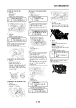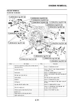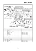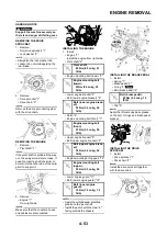
4-46
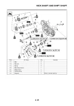
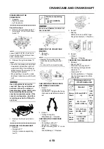
KICK SHAFT AND SHIFT SHAFT
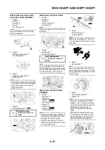
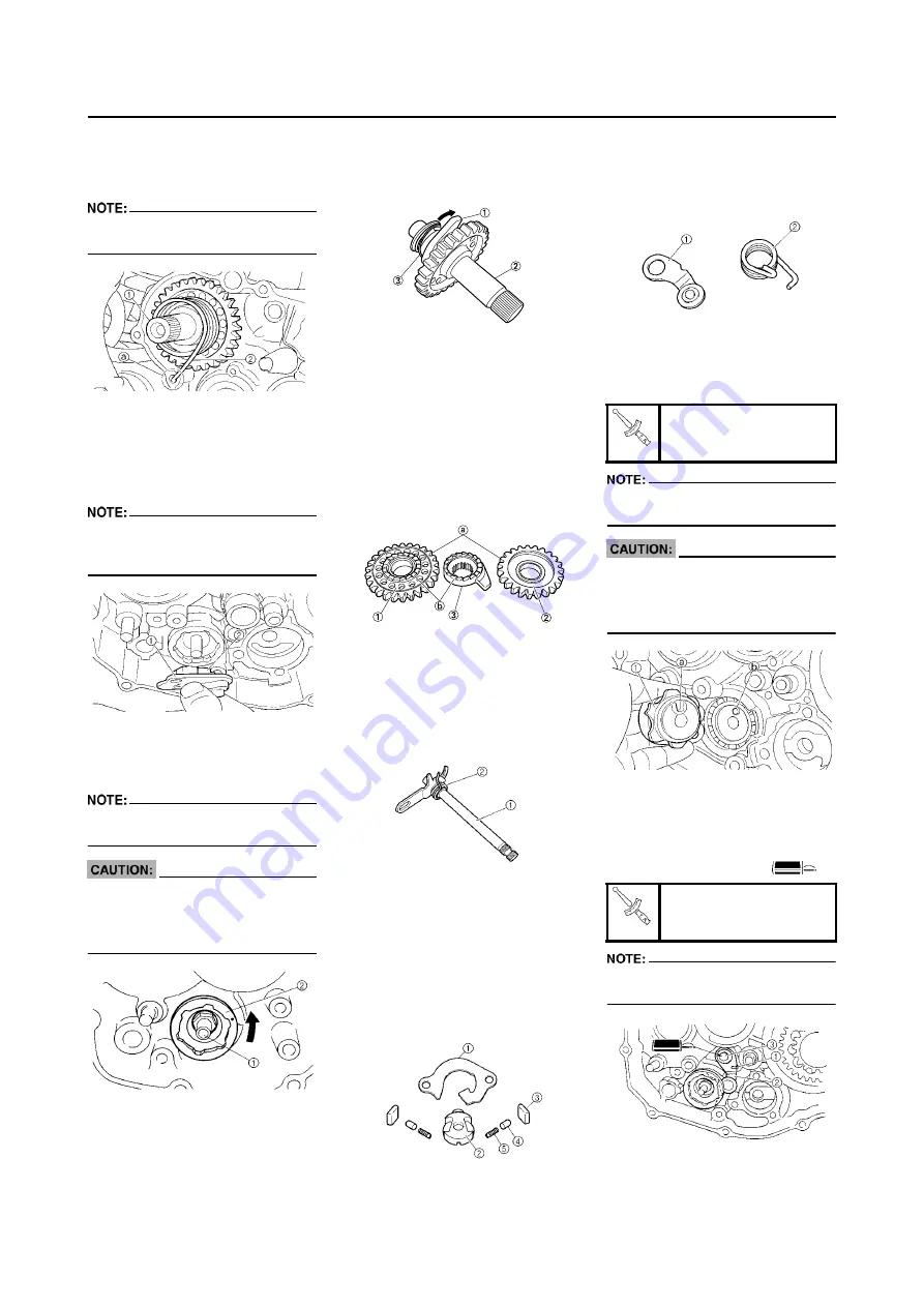
REMOVING THE KICK SHAFT
ASSEMBLY
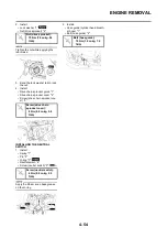
1. Remove:
• Kick shaft assembly "1"
Unhook the torsion spring "2" from
the hole "a" in the crankcase.
REMOVING THE SHIFT GUIDE
AND SHIFT LEVER ASSEMBLY
1. Remove:
• Bolt (shift guide)
• Shift guide "1"
• Shift lever assembly "2"
The shift lever assembly is disassem-
bled at the same time as the shift
guide.
REMOVING THE SEGMENT
1. Remove:
• Bolt (segment) "1"
• Segment "2"
Turn the segment counterclockwise
until it stops and loosen the bolt.
If the segment gets an impact, it
may be damaged. Take care not to
give an impact to the segment
when removing the bolt.
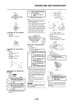
CHECKING THE KICK SHAFT AND
RATCHET WHEEL
1. Check:
• Ratchet wheel "1" smooth move-
ment
Unsmooth movement
→
Replace.
• Kick shaft "2"
Wear/damage
→
Replace.
• Spring "3"
Broken
→
Replace.
CHECKING THE KICK GEAR, KICK
IDLE GEAR AND RATCHET
WHEEL
1. Inspect:
• Kick gear "1"
• Kick idle gear "2"
• Ratchet wheel "3"
• Gear teeth "a"
• Ratchet teeth "b"
Wear/damage
→
Replace.
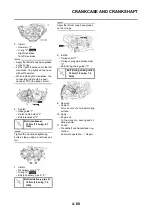
CHECKING THE SHIFT SHAFT
1. Inspect:
• Shift shaft "1"
Bend/damage
→
Replace.
• Spring "2"
Broken
→
Replace.
CHECKING THE SHIFT GUIDE AND
SHIFT LEVER ASSEMBLY
1. Inspect:
• Shift guide "1"
• Shift lever "2"
• Pawl "3"
• Pawl pin "4"
• Spring "5"
Wear/damage
→
Replace.
CHECKING THE STOPPER LEVER
1. Inspect:
• Stopper lever "1"
Wear/damage
→
Replace.
• Torsion spring "2"
Broken
→
Replace.
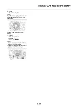
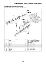
INSTALLING THE SEGMENT
1. Install:
• Segment "1"
• Bolt (segment)
Align the notch "a" on the segment
with the pin "b" on the shift cam.
If the segment gets an impact, it
may be damaged. Take care not to
give an impact to the segment
when tightening the bolt.
INSTALLING THE STOPPER
LEVER
1. Install:
• Torsion spring "1"
• Stopper lever "2"
• Bolt (stopper lever) "3"
Align the stopper lever roller with the
slot on segment.
Bolt (segment):
30 Nm (3.0 m•kg, 22
ft•lb)
Bolt (stopper lever):
10 Nm (1.0 m•kg, 7.2
ft•lb)
Содержание YZ250F X 2008
Страница 2: ......
Страница 3: ...YZ250F X 5XC 28199 34 E0 2008 OWNER S SERVICE MANUAL ...
Страница 4: ......
Страница 39: ...2 17 LUBRICATION DIAGRAMS 1 Crankshaft 2 Oil filter element 3 Oil tank 4 Oil hose A From oil pump ...
Страница 59: ...3 13 ENGINE INTAKE EXHAUST ...
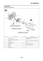
Страница 110: ...4 41 OIL PUMP 15 Rotor housing 1 Order Part name Q ty Remarks ...
Страница 161: ...5 29 STEERING 9 Bearing race 2 Refer to removal section Order Part name Q ty Remarks ...
Страница 170: ...5 38 REAR SHOCK ABSORBER 12 Bearing 2 Refer to removal section Order Part name Q ty Remarks ...
Страница 191: ......
Страница 192: ...PRINTED IN JAPAN E PRINTED ON RECYCLED PAPER YAMAHA MOTOR CO LTD 2500 SHINGAI IWATA SHIZUOKA JAPAN ...


