


LIST OF SELF-DIAGNOSTIC AND FAIL-SAFE ACTIONS
9-6
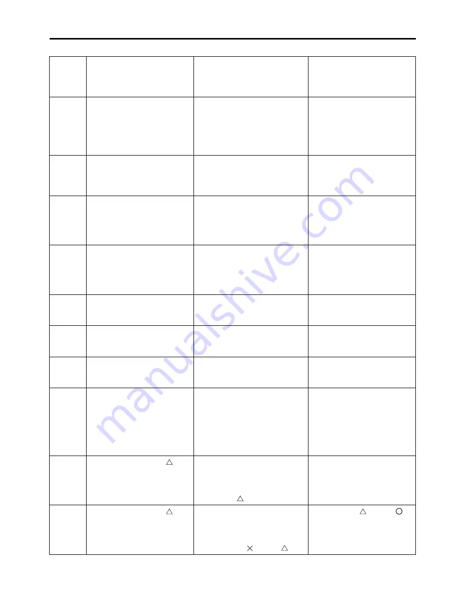
SENSOR OPERATION TABLE
Diag-
nostic
code
No.
Item
Display
Procedure
01
Throttle position sensor sig-
nal
• Fully closed position
• Fully opened position
• 11–14
• 109–116
• Check with throttle valve
fully closed.
• Check with throttle valve
fully open.
03
Intake air pressure
Displays the intake air pres-
sure.
Operate the throttle while
pushing the start switch. (If
the display value changes,
the performance is OK.)
05
Intake air temperature
Displays the intake air tem-
perature.
Compare the actually mea-
sured intake air tempera-
ture with the Yamaha
diagnostic tool display val-
ue.
06
Coolant temperature
When engine is cold: Dis-
plays temperature closer to
air temperature.
When engine is hot: Displays
current coolant temperature.
Compare the actually mea-
sured coolant temperature
with the Yamaha diagnostic
tool display value.
08
Lean angle sensor
• Upright
• Overturned
Displays the output voltage.
• 0.4–1.4
• 3.6–4.5
Remove the lean angle
sensor, and incline it more
than 45 degrees.
09
Monitor voltage
Displays the fuel system volt-
age.
• Approximately 12.0 (V)
—
21
Neutral switch
• Gear in neutral
• Gear not in neutral
• ON
• OFF
Operate the shift pedal.
60
EEPROM fault code display
• No fault
• CO adjustment value
• Setting tool adjustment
values 0–8 for fuel injec-
tion amount or ignition tim-
ing
• 00
• 01
• 07
—
61
Malfunction history ( )
code display *1
• There is no history.
• There is some history.
• 00
• Other: Displays the fault
code of ( ).
—
62
Malfunction history ( )
code erasure *1
• There is no history.
• There is some history.
• 00
• Other: Displays the total
number of ( ) and ( ).
Replace all ( ) with ( )
by the operation start pro-
cessing.
Содержание YZ 2018 Series
Страница 6: ...EASB916006 YAMAHA MOTOR CORPORATION U S A YZ MOTORCYCLE LIMITED WARRANTY...
Страница 10: ......
Страница 40: ...MOTORCYCLE CARE AND STORAGE 1 28...
Страница 51: ...ELECTRICAL SPECIFICATIONS 2 10 Fuse s Main fuse 15 0 A Spare fuse 15 0 A Radiator fan motor fuse 5 0 A...
Страница 64: ...LUBRICATION SYSTEM CHART AND DIAGRAMS 2 23...
Страница 66: ...LUBRICATION SYSTEM CHART AND DIAGRAMS 2 25...
Страница 67: ...LUBRICATION SYSTEM CHART AND DIAGRAMS 2 26 1 Exhaust camshaft 2 Intake camshaft 3 Oil filter element 4 Oil pump...
Страница 68: ...LUBRICATION SYSTEM CHART AND DIAGRAMS 2 27...
Страница 69: ...LUBRICATION SYSTEM CHART AND DIAGRAMS 2 28 1 Camshaft 2 Oil pressure check bolt 3 Oil filter element 4 Oil pump...
Страница 70: ...CABLE ROUTING DIAGRAM 2 29 EASB29B065 CABLE ROUTING DIAGRAM...
Страница 72: ...CABLE ROUTING DIAGRAM 2 31...
Страница 74: ...CABLE ROUTING DIAGRAM 2 33...
Страница 76: ...CABLE ROUTING DIAGRAM 2 35...
Страница 78: ...CABLE ROUTING DIAGRAM 2 37...
Страница 80: ...CABLE ROUTING DIAGRAM 2 39...
Страница 82: ...CABLE ROUTING DIAGRAM 2 41...
Страница 84: ...CABLE ROUTING DIAGRAM 2 43...
Страница 235: ...ELECTRIC STARTER 5 38 5 Install Bolt 1 O ring 2 TIP Apply the lithium soap based grease on the O ring New...
Страница 255: ...OIL PUMP AND BALANCER GEAR 5 58 a 2 10 b 2 9 1 b 5 3 a 4 10 5 9 3 E c d 6 7 8 8 b 6...
Страница 276: ...TRANSMISSION 5 79...
Страница 290: ...FUEL TANK 7 5 A Left B Right 1 1 A 0 mm 0 in B 1 1 15 mm 0 59 in...
Страница 296: ...THROTTLE BODY 7 11...
Страница 299: ......
Страница 313: ...CHARGING SYSTEM 8 14...
Страница 321: ...COOLING SYSTEM For JPN 8 22...
Страница 351: ...FUEL PUMP SYSTEM 8 52 EASB29B345...
Страница 352: ...ELECTRICAL COMPONENTS 8 53 ELECTRICAL COMPONENTS EASB29B346 9 10 11 1 3 2 4 5 6 7 8...
Страница 354: ...ELECTRICAL COMPONENTS 8 55 11 10 9 2 3 1 6 7 8 4 5...
Страница 356: ...ELECTRICAL COMPONENTS 8 57 EASB29B347 CHECKING THE SWITCHES 4 1 3 2 B B Sb B B B B B B B B...
Страница 357: ...ELECTRICAL COMPONENTS 8 58 1 Engine stop switch 2 Neutral switch 3 Clutch switch 4 Start switch...
Страница 372: ...ELECTRICAL COMPONENTS 8 73 c Measure the fuel injector resistance...