ELECTRICAL COMPONENTS
8-63
ECA
NOTICE
• Do not use a high-rate battery charger
since it forces a high-amperage current
into the battery quickly and can cause bat-
tery overheating and battery plate dam-
age.
• If it is impossible to regulate the charging
current on the battery charger, be careful
not to overcharge the battery.
• When charging a battery, be sure to re-
move it from the vehicle. (If charging has
to be done with the battery mounted on the
vehicle, disconnect the negative battery
lead from the battery terminal.)
• To reduce the chance of sparks, do not
plug in the battery charger until the battery
charger leads are connected to the bat-
tery.
• Before removing the battery charger lead
clips from the battery terminals, be sure to
turn off the battery charger.
• Make sure the battery charger lead clips
are in full contact with the battery terminal
and that they are not shorted. A corroded
battery charger lead clip may generate
heat in the contact area and a weak clip
spring may cause sparks.
• If the battery becomes hot to the touch at
any time during the charging process, dis-
connect the battery charger and let the
battery cool before reconnecting it. Hot
batteries can explode!
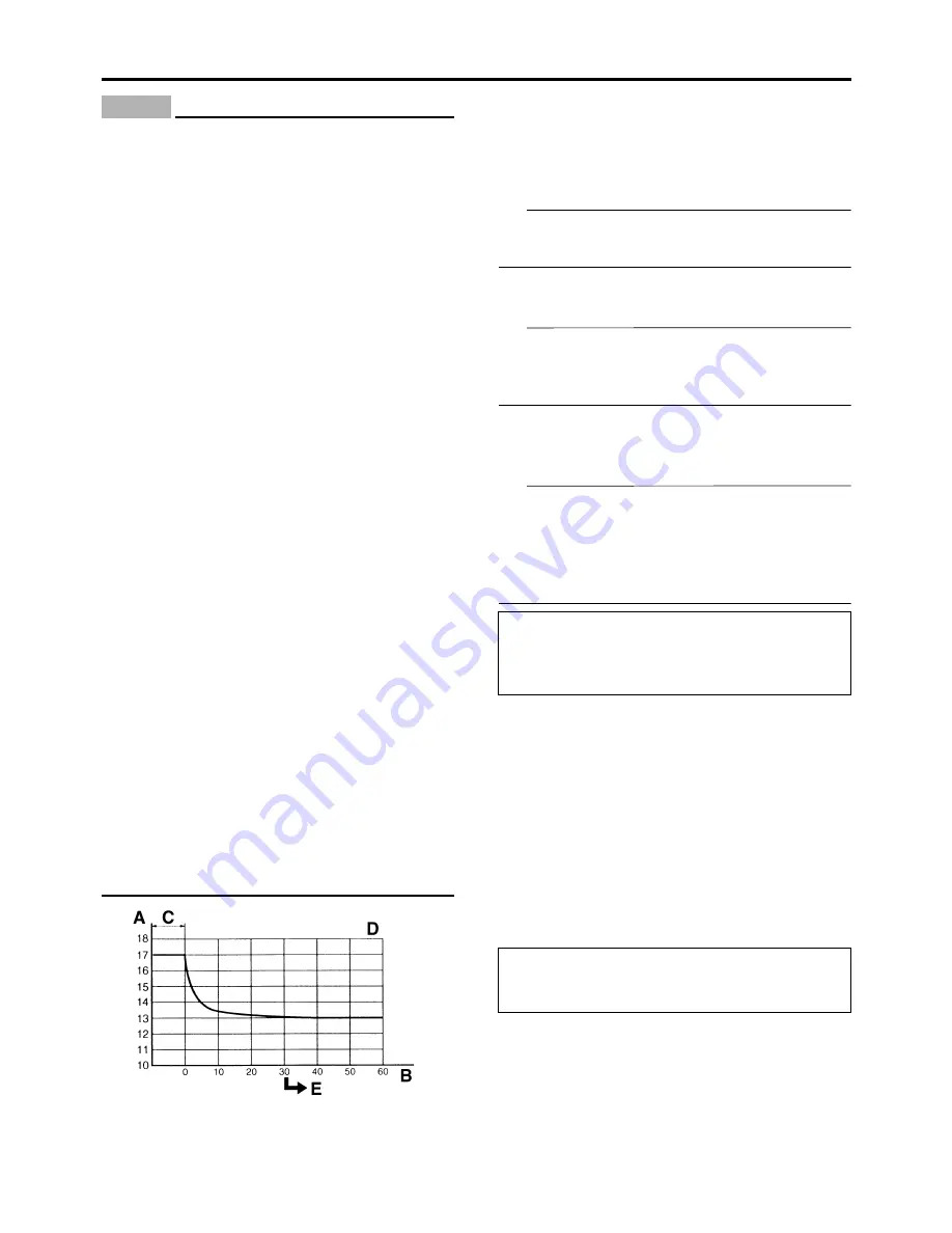
• As shown in the following illustration, the
open-circuit voltage of a VRLA (Valve Reg-
ulated Lead Acid) battery stabilizes about
30 minutes after charging has been com-
pleted. Therefore, wait 30 minutes after
charging is completed before measuring
the open-circuit voltage.
▼▼▼▼▼▼▼▼▼▼▼▼▼▼▼▼▼▼▼▼▼▼▼▼▼▼▼▼▼▼▼▼
Charging method using a variable-cur-
rent (voltage) charger
a. Measure the open-circuit voltage prior to
charging.
TIP
Voltage should be measured 30 minutes after
the engine is stopped.
b. Connect a charger and ammeter to the bat-
tery and start charging.
TIP
Set the charging voltage to 16–17 V. If the set-
ting is lower, charging will be insufficient. If too
high, the battery will be over-charged.
c. Make sure that the current is higher than the
standard charging current written on the bat-
tery.
TIP
If the current is lower than the standard charg-
ing current written on the battery, set the charg-
ing voltage adjust dial at 20–24 V and monitor
the amperage for 3–5 minutes to check the bat-
tery.
d. Adjust the voltage so that the current is at
the standard charging level.
e. Set the time according to the charging time
suitable for the open-circuit voltage.
f. If charging requires more than 5 hours, it is
advisable to check the charging current after
a lapse of 5 hours. If there is any change in
the amperage, readjust the voltage to obtain
the standard charging current.
g. Measure the battery open-circuit voltage af-
ter leaving the battery unused for more than
30 minutes.
▲▲▲▲▲▲▲▲▲▲▲▲▲▲▲▲▲▲▲▲▲▲▲▲▲▲▲▲▲▲▲▲
▼▼▼▼▼▼▼▼▼▼▼▼▼▼▼▼▼▼▼▼▼▼▼▼▼▼▼▼▼▼▼▼
Charging method using a constant volt-
age charger
a. Measure the open-circuit voltage prior to
charging.
A. Open-circuit voltage (V)
B. Time (minutes)
C. Charging
D. Ambient temperature 20 °C (68 °F)
E. Check the open-circuit voltage.
• Standard charging current is reached
Battery is good.
• Standard charging current is not reached
Replace the battery.
12.8 V or more --- Charging is complete.
12.7 V or less --- Recharging is required.
Under 12.0 V --- Replace the battery.
Содержание YZ 2018 Series
Страница 6: ...EASB916006 YAMAHA MOTOR CORPORATION U S A YZ MOTORCYCLE LIMITED WARRANTY...
Страница 10: ......
Страница 40: ...MOTORCYCLE CARE AND STORAGE 1 28...
Страница 51: ...ELECTRICAL SPECIFICATIONS 2 10 Fuse s Main fuse 15 0 A Spare fuse 15 0 A Radiator fan motor fuse 5 0 A...
Страница 64: ...LUBRICATION SYSTEM CHART AND DIAGRAMS 2 23...
Страница 66: ...LUBRICATION SYSTEM CHART AND DIAGRAMS 2 25...
Страница 67: ...LUBRICATION SYSTEM CHART AND DIAGRAMS 2 26 1 Exhaust camshaft 2 Intake camshaft 3 Oil filter element 4 Oil pump...
Страница 68: ...LUBRICATION SYSTEM CHART AND DIAGRAMS 2 27...
Страница 69: ...LUBRICATION SYSTEM CHART AND DIAGRAMS 2 28 1 Camshaft 2 Oil pressure check bolt 3 Oil filter element 4 Oil pump...
Страница 70: ...CABLE ROUTING DIAGRAM 2 29 EASB29B065 CABLE ROUTING DIAGRAM...
Страница 72: ...CABLE ROUTING DIAGRAM 2 31...
Страница 74: ...CABLE ROUTING DIAGRAM 2 33...
Страница 76: ...CABLE ROUTING DIAGRAM 2 35...
Страница 78: ...CABLE ROUTING DIAGRAM 2 37...
Страница 80: ...CABLE ROUTING DIAGRAM 2 39...
Страница 82: ...CABLE ROUTING DIAGRAM 2 41...
Страница 84: ...CABLE ROUTING DIAGRAM 2 43...
Страница 235: ...ELECTRIC STARTER 5 38 5 Install Bolt 1 O ring 2 TIP Apply the lithium soap based grease on the O ring New...
Страница 255: ...OIL PUMP AND BALANCER GEAR 5 58 a 2 10 b 2 9 1 b 5 3 a 4 10 5 9 3 E c d 6 7 8 8 b 6...
Страница 276: ...TRANSMISSION 5 79...
Страница 290: ...FUEL TANK 7 5 A Left B Right 1 1 A 0 mm 0 in B 1 1 15 mm 0 59 in...
Страница 296: ...THROTTLE BODY 7 11...
Страница 299: ......
Страница 313: ...CHARGING SYSTEM 8 14...
Страница 321: ...COOLING SYSTEM For JPN 8 22...
Страница 351: ...FUEL PUMP SYSTEM 8 52 EASB29B345...
Страница 352: ...ELECTRICAL COMPONENTS 8 53 ELECTRICAL COMPONENTS EASB29B346 9 10 11 1 3 2 4 5 6 7 8...
Страница 354: ...ELECTRICAL COMPONENTS 8 55 11 10 9 2 3 1 6 7 8 4 5...
Страница 356: ...ELECTRICAL COMPONENTS 8 57 EASB29B347 CHECKING THE SWITCHES 4 1 3 2 B B Sb B B B B B B B B...
Страница 357: ...ELECTRICAL COMPONENTS 8 58 1 Engine stop switch 2 Neutral switch 3 Clutch switch 4 Start switch...
Страница 372: ...ELECTRICAL COMPONENTS 8 73 c Measure the fuel injector resistance...


