FUEL INJECTION SYSTEM
8-38
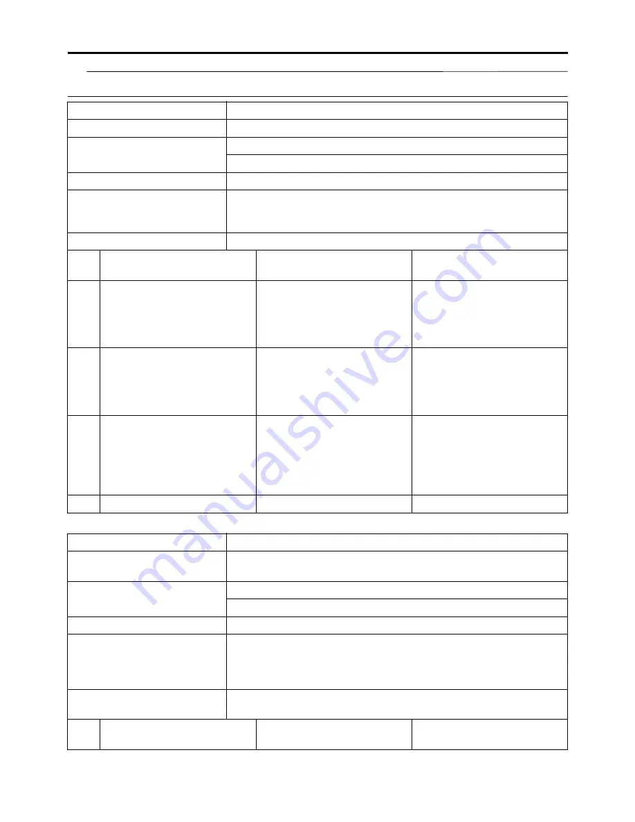
TIP
Before troubleshooting, disconnect the starter motor lead from the starter relay.
Fault code No.
30
Item
Latch up detected.
Fail-safe system
Unable to start engine
Unable to drive vehicle
Diagnostic code No.
08
Diagnostic tool display
Lean angle sensor output voltage
• 0.4–1.4 (upright)
• 3.6–4.5 (overturned)
Procedure
Remove the lean angle sensor and incline it more than 45 degrees.
Item
Probable cause of malfunc-
tion and check
Maintenance job
Confirmation of service
completion
1
The vehicle has overturned.
Raise the vehicle upright.
Push the start switch.
Fault code number is not dis-
played
Service is finished.
Fault code number is dis-
played
Go to item 2.
2
Installed condition of lean an-
gle sensor.
Check the installed direction
and condition of the sensor.
Push the start switch.
Fault code number is not dis-
played
Service is finished.
Fault code number is dis-
played
Go to item 3.
3
Defective lean angle sensor.
Execute the diagnostic mode.
(Code No. 08)
Replace if defective.
Refer to “CHECKING THE
LEAN ANGLE SENSOR” on
page 8-67.
Push the start switch.
Fault code number is not dis-
played
Service is finished.
Fault code number is dis-
played
Go to item 4.
4
Malfunction in ECU.
Replace the ECU.
Fault code No.
33
Item
Ignition coil: open or short circuit detected in the primary lead
of the ignition coil.
Fail-safe system
Unable to start engine
Unable to drive vehicle
Diagnostic code No.
30
Actuation
Actuates the ignition coil five times at one-second intervals.
The engine trouble warning light and the “WARNING” on the
Yamaha diagnostic tool screen come on each time the ignition coil
is actuated.
Procedure
Check that a spark is generated five times.
• Connect an ignition checker.
Item
Probable cause of malfunc-
tion and check
Maintenance job
Confirmation of service
completion
Содержание YZ 2018 Series
Страница 6: ...EASB916006 YAMAHA MOTOR CORPORATION U S A YZ MOTORCYCLE LIMITED WARRANTY...
Страница 10: ......
Страница 40: ...MOTORCYCLE CARE AND STORAGE 1 28...
Страница 51: ...ELECTRICAL SPECIFICATIONS 2 10 Fuse s Main fuse 15 0 A Spare fuse 15 0 A Radiator fan motor fuse 5 0 A...
Страница 64: ...LUBRICATION SYSTEM CHART AND DIAGRAMS 2 23...
Страница 66: ...LUBRICATION SYSTEM CHART AND DIAGRAMS 2 25...
Страница 67: ...LUBRICATION SYSTEM CHART AND DIAGRAMS 2 26 1 Exhaust camshaft 2 Intake camshaft 3 Oil filter element 4 Oil pump...
Страница 68: ...LUBRICATION SYSTEM CHART AND DIAGRAMS 2 27...
Страница 69: ...LUBRICATION SYSTEM CHART AND DIAGRAMS 2 28 1 Camshaft 2 Oil pressure check bolt 3 Oil filter element 4 Oil pump...
Страница 70: ...CABLE ROUTING DIAGRAM 2 29 EASB29B065 CABLE ROUTING DIAGRAM...
Страница 72: ...CABLE ROUTING DIAGRAM 2 31...
Страница 74: ...CABLE ROUTING DIAGRAM 2 33...
Страница 76: ...CABLE ROUTING DIAGRAM 2 35...
Страница 78: ...CABLE ROUTING DIAGRAM 2 37...
Страница 80: ...CABLE ROUTING DIAGRAM 2 39...
Страница 82: ...CABLE ROUTING DIAGRAM 2 41...
Страница 84: ...CABLE ROUTING DIAGRAM 2 43...
Страница 235: ...ELECTRIC STARTER 5 38 5 Install Bolt 1 O ring 2 TIP Apply the lithium soap based grease on the O ring New...
Страница 255: ...OIL PUMP AND BALANCER GEAR 5 58 a 2 10 b 2 9 1 b 5 3 a 4 10 5 9 3 E c d 6 7 8 8 b 6...
Страница 276: ...TRANSMISSION 5 79...
Страница 290: ...FUEL TANK 7 5 A Left B Right 1 1 A 0 mm 0 in B 1 1 15 mm 0 59 in...
Страница 296: ...THROTTLE BODY 7 11...
Страница 299: ......
Страница 313: ...CHARGING SYSTEM 8 14...
Страница 321: ...COOLING SYSTEM For JPN 8 22...
Страница 351: ...FUEL PUMP SYSTEM 8 52 EASB29B345...
Страница 352: ...ELECTRICAL COMPONENTS 8 53 ELECTRICAL COMPONENTS EASB29B346 9 10 11 1 3 2 4 5 6 7 8...
Страница 354: ...ELECTRICAL COMPONENTS 8 55 11 10 9 2 3 1 6 7 8 4 5...
Страница 356: ...ELECTRICAL COMPONENTS 8 57 EASB29B347 CHECKING THE SWITCHES 4 1 3 2 B B Sb B B B B B B B B...
Страница 357: ...ELECTRICAL COMPONENTS 8 58 1 Engine stop switch 2 Neutral switch 3 Clutch switch 4 Start switch...
Страница 372: ...ELECTRICAL COMPONENTS 8 73 c Measure the fuel injector resistance...


