FUEL INJECTION SYSTEM
8-36
TIP
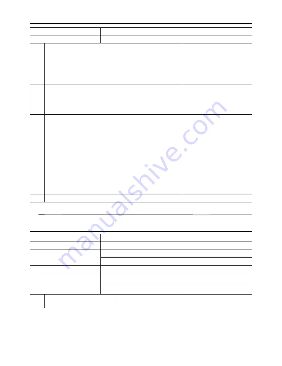
• Make sure that the engine is completely cool before checking the intake air temperature sensor.
• Before troubleshooting, disconnect the starter motor lead from the starter relay.
3
Wire harness continuity.
Open or short circuit
Re-
place the wire harness.
Between coolant temperature
sensor coupler and ECU cou-
pler.
green/white–green/white
black/blue–black/blue
Push the start switch.
Fault code number is not dis-
played
Service is finished.
Fault code number is dis-
played
Go to item 4.
4
Installed condition of coolant
temperature sensor.
Check for looseness or
pinching.
Improperly installed sensor
Reinstall or replace the
sensor.
Push the start switch.
Fault code number is not dis-
played
Service is finished.
Fault code number is dis-
played
Go to item 5.
5
Defective coolant tempera-
ture sensor.
Execute the diagnostic mode.
(Code No. 06)
When engine is cold:
Displayed temperature is
close to the ambient temper-
ature.
The displayed temperature is
not close to the ambient tem-
perature.
Check the cool-
ant temperature sensor.
Replace if defective.
Refer to “CHECKING THE
COOLANT TEMPERATURE
SENSOR” on page 8-70.
Push the start switch.
Fault code number is not dis-
played
Service is finished.
Fault code number is dis-
played
Go to item 6.
6
Malfunction in ECU.
Replace the ECU.
Fault code No.
22
Item
Intake air temperature sensor: open or short circuit detected.
Fail-safe system
Able to start engine
Able to drive vehicle
Diagnostic code No.
05
Diagnostic tool display
Displays the intake air temperature.
Procedure
Compare the actually measured intake air temperature with the
Yamaha diagnostic tool display value.
Item
Probable cause of malfunc-
tion and check
Maintenance job
Confirmation of service
completion
Fault code No.
21
Item
Coolant temperature sensor: open or short circuit detected.
Содержание YZ 2018 Series
Страница 6: ...EASB916006 YAMAHA MOTOR CORPORATION U S A YZ MOTORCYCLE LIMITED WARRANTY...
Страница 10: ......
Страница 40: ...MOTORCYCLE CARE AND STORAGE 1 28...
Страница 51: ...ELECTRICAL SPECIFICATIONS 2 10 Fuse s Main fuse 15 0 A Spare fuse 15 0 A Radiator fan motor fuse 5 0 A...
Страница 64: ...LUBRICATION SYSTEM CHART AND DIAGRAMS 2 23...
Страница 66: ...LUBRICATION SYSTEM CHART AND DIAGRAMS 2 25...
Страница 67: ...LUBRICATION SYSTEM CHART AND DIAGRAMS 2 26 1 Exhaust camshaft 2 Intake camshaft 3 Oil filter element 4 Oil pump...
Страница 68: ...LUBRICATION SYSTEM CHART AND DIAGRAMS 2 27...
Страница 69: ...LUBRICATION SYSTEM CHART AND DIAGRAMS 2 28 1 Camshaft 2 Oil pressure check bolt 3 Oil filter element 4 Oil pump...
Страница 70: ...CABLE ROUTING DIAGRAM 2 29 EASB29B065 CABLE ROUTING DIAGRAM...
Страница 72: ...CABLE ROUTING DIAGRAM 2 31...
Страница 74: ...CABLE ROUTING DIAGRAM 2 33...
Страница 76: ...CABLE ROUTING DIAGRAM 2 35...
Страница 78: ...CABLE ROUTING DIAGRAM 2 37...
Страница 80: ...CABLE ROUTING DIAGRAM 2 39...
Страница 82: ...CABLE ROUTING DIAGRAM 2 41...
Страница 84: ...CABLE ROUTING DIAGRAM 2 43...
Страница 235: ...ELECTRIC STARTER 5 38 5 Install Bolt 1 O ring 2 TIP Apply the lithium soap based grease on the O ring New...
Страница 255: ...OIL PUMP AND BALANCER GEAR 5 58 a 2 10 b 2 9 1 b 5 3 a 4 10 5 9 3 E c d 6 7 8 8 b 6...
Страница 276: ...TRANSMISSION 5 79...
Страница 290: ...FUEL TANK 7 5 A Left B Right 1 1 A 0 mm 0 in B 1 1 15 mm 0 59 in...
Страница 296: ...THROTTLE BODY 7 11...
Страница 299: ......
Страница 313: ...CHARGING SYSTEM 8 14...
Страница 321: ...COOLING SYSTEM For JPN 8 22...
Страница 351: ...FUEL PUMP SYSTEM 8 52 EASB29B345...
Страница 352: ...ELECTRICAL COMPONENTS 8 53 ELECTRICAL COMPONENTS EASB29B346 9 10 11 1 3 2 4 5 6 7 8...
Страница 354: ...ELECTRICAL COMPONENTS 8 55 11 10 9 2 3 1 6 7 8 4 5...
Страница 356: ...ELECTRICAL COMPONENTS 8 57 EASB29B347 CHECKING THE SWITCHES 4 1 3 2 B B Sb B B B B B B B B...
Страница 357: ...ELECTRICAL COMPONENTS 8 58 1 Engine stop switch 2 Neutral switch 3 Clutch switch 4 Start switch...
Страница 372: ...ELECTRICAL COMPONENTS 8 73 c Measure the fuel injector resistance...


