REAR SHOCK ABSORBER ASSEMBLY
4-58
EASB29B181
HANDLING THE REAR SHOCK ABSORBER
EWA
WARNING
This rear shock absorber contains highly
compressed nitrogen gas. Before handling
the rear shock absorber, read and make
sure that you understand the following in-
formation. The manufacturer cannot be held
responsible for property damage or person-
al injury that may result from improper han-
dling of the rear shock absorber.
• Do not tamper or attempt to open the rear
shock absorber.
• Do not subject the rear shock absorber to
an open flame or any other source of high
heat. High heat can cause an explosion
due to excessive gas pressure.
• Do not deform or damage the rear shock
absorber in any way. Rear shock absorber
damage will result in poor damping perfor-
mance.
TIP
A break-in is required up to about 50 km of run-
ning.
EASB29B182
DISPOSING OF A REAR SHOCK ABSORB-
ER
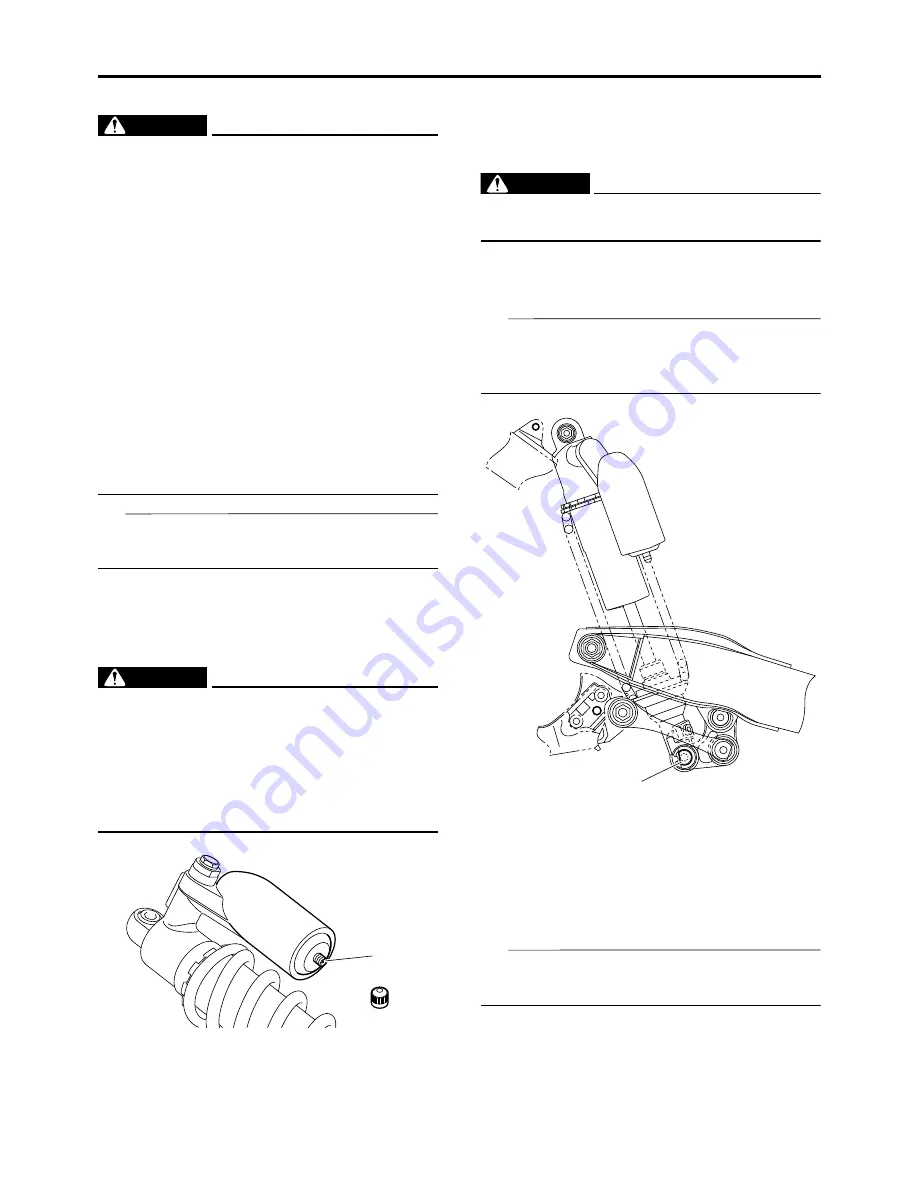
Before disposing the rear shock absorber, be
sure to extract the nitrogen gas from valve “1”.
EWA
WARNING
• Wear protective glasses to prevent your
eyes from damage due to possible gas or
metal chips scattered.
• To dispose of a damaged or a worn-out
rear shock absorber, take the unit to your
Yamaha dealer for this disposal proce-
dure.
EASB29B183
REMOVING THE REAR SHOCK ABSORBER
ASSEMBLY
1. Use a suitable stand to raise the rear wheel
off the ground.
EWA
WARNING
Securely support the vehicle so that there is
no danger of it falling over.
2. Remove:
• Rear shock absorber assembly lower bolt
“1”
TIP
While removing the rear shock absorber as-
sembly lower bolt, hold the swingarm so that it
does not drop down.
3. Remove:
• Rear shock absorber assembly upper bolt
• Rear shock absorber assembly
EASB29B184
REMOVING THE BEARING
1. Remove:
• Stopper ring (upper bearing) “1”
TIP
Press in the bearing while pressing its outer
race and remove the stopper ring.
1
1
Содержание YZ 2018 Series
Страница 6: ...EASB916006 YAMAHA MOTOR CORPORATION U S A YZ MOTORCYCLE LIMITED WARRANTY...
Страница 10: ......
Страница 40: ...MOTORCYCLE CARE AND STORAGE 1 28...
Страница 51: ...ELECTRICAL SPECIFICATIONS 2 10 Fuse s Main fuse 15 0 A Spare fuse 15 0 A Radiator fan motor fuse 5 0 A...
Страница 64: ...LUBRICATION SYSTEM CHART AND DIAGRAMS 2 23...
Страница 66: ...LUBRICATION SYSTEM CHART AND DIAGRAMS 2 25...
Страница 67: ...LUBRICATION SYSTEM CHART AND DIAGRAMS 2 26 1 Exhaust camshaft 2 Intake camshaft 3 Oil filter element 4 Oil pump...
Страница 68: ...LUBRICATION SYSTEM CHART AND DIAGRAMS 2 27...
Страница 69: ...LUBRICATION SYSTEM CHART AND DIAGRAMS 2 28 1 Camshaft 2 Oil pressure check bolt 3 Oil filter element 4 Oil pump...
Страница 70: ...CABLE ROUTING DIAGRAM 2 29 EASB29B065 CABLE ROUTING DIAGRAM...
Страница 72: ...CABLE ROUTING DIAGRAM 2 31...
Страница 74: ...CABLE ROUTING DIAGRAM 2 33...
Страница 76: ...CABLE ROUTING DIAGRAM 2 35...
Страница 78: ...CABLE ROUTING DIAGRAM 2 37...
Страница 80: ...CABLE ROUTING DIAGRAM 2 39...
Страница 82: ...CABLE ROUTING DIAGRAM 2 41...
Страница 84: ...CABLE ROUTING DIAGRAM 2 43...
Страница 235: ...ELECTRIC STARTER 5 38 5 Install Bolt 1 O ring 2 TIP Apply the lithium soap based grease on the O ring New...
Страница 255: ...OIL PUMP AND BALANCER GEAR 5 58 a 2 10 b 2 9 1 b 5 3 a 4 10 5 9 3 E c d 6 7 8 8 b 6...
Страница 276: ...TRANSMISSION 5 79...
Страница 290: ...FUEL TANK 7 5 A Left B Right 1 1 A 0 mm 0 in B 1 1 15 mm 0 59 in...
Страница 296: ...THROTTLE BODY 7 11...
Страница 299: ......
Страница 313: ...CHARGING SYSTEM 8 14...
Страница 321: ...COOLING SYSTEM For JPN 8 22...
Страница 351: ...FUEL PUMP SYSTEM 8 52 EASB29B345...
Страница 352: ...ELECTRICAL COMPONENTS 8 53 ELECTRICAL COMPONENTS EASB29B346 9 10 11 1 3 2 4 5 6 7 8...
Страница 354: ...ELECTRICAL COMPONENTS 8 55 11 10 9 2 3 1 6 7 8 4 5...
Страница 356: ...ELECTRICAL COMPONENTS 8 57 EASB29B347 CHECKING THE SWITCHES 4 1 3 2 B B Sb B B B B B B B B...
Страница 357: ...ELECTRICAL COMPONENTS 8 58 1 Engine stop switch 2 Neutral switch 3 Clutch switch 4 Start switch...
Страница 372: ...ELECTRICAL COMPONENTS 8 73 c Measure the fuel injector resistance...


