HANDLEBAR
4-33
EASB29B167
REMOVING THE HANDLEBAR
1. Stand the vehicle on a level surface.
EWA
WARNING
Securely support the vehicle so that there is
no danger of it falling over.
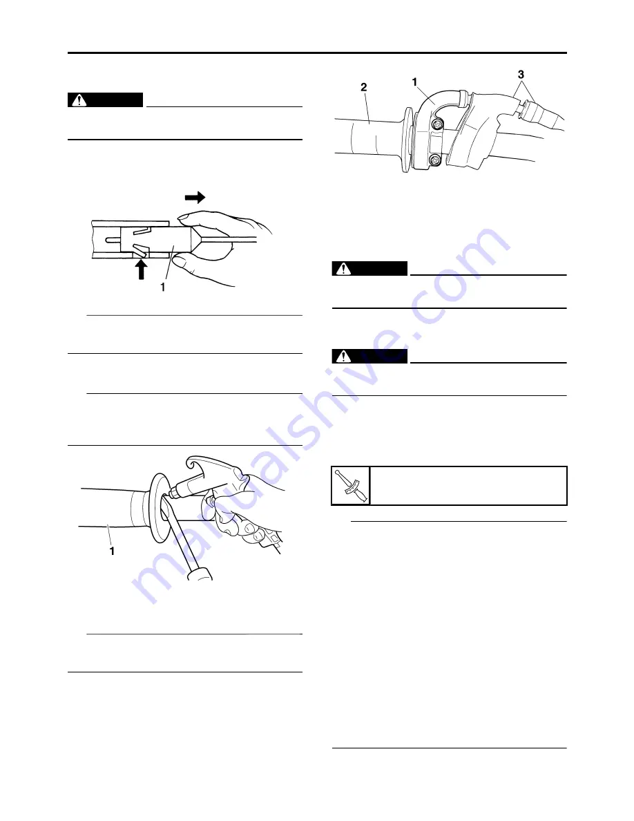
2. Remove:
• Clutch switch “1”
TIP
Press the projection, and remove it from the
clutch lever assembly.
3. Remove:
• Handlebar grip “1”
TIP
Blow compressed air between the left handle-
bar and the handlebar grip, and gradually push
the grip off the handlebar.
4. Remove:
• Throttle cable housings “1”
• Throttle grip “2”
TIP
While removing the throttle cable housing, pull
back the rubber cover “3”.
EASB29B168
CHECKING THE HANDLEBAR
1. Check:
• Handlebar
Bends/cracks/damage
Replace.
EWA
WARNING
Do not attempt to straighten a bent handle-
bar as this may dangerously weaken it.
EASB29B169
INSTALLING THE HANDLEBAR
1. Stand the vehicle upright on a level surface.
EWA
WARNING
Securely support the vehicle so that there is
no danger of it falling over.
2. Install:
• Damper “1”
• Lower handlebar holders“2” (temporarily)
• Handlebar “3”
• Upper handlebar holders “4”
TIP
• Install the lower handlebar holders with them
side having the greater distance “a” from the
mounting bolt center facing forward.
• Installing the lower handlebar holders in the
reverse direction allow the front-to-rear offset
amount of the handlebar position to be
changed.
• The upper handlebar holders should be in-
stalled with the punch marks “b” facing for-
ward.
• When installing the handlebar, make sure that
right and left marks “c” are in place identically
on both sides.
• Install the handlebar so that the projection “d”
of the upper handlebar holders is positioned
at the mark on the handlebar as shown.
Upper handlebar holder bolt
28 N·m (2.8 kgf·m, 21 lb·ft)
T
R
.
.
Содержание YZ 2018 Series
Страница 6: ...EASB916006 YAMAHA MOTOR CORPORATION U S A YZ MOTORCYCLE LIMITED WARRANTY...
Страница 10: ......
Страница 40: ...MOTORCYCLE CARE AND STORAGE 1 28...
Страница 51: ...ELECTRICAL SPECIFICATIONS 2 10 Fuse s Main fuse 15 0 A Spare fuse 15 0 A Radiator fan motor fuse 5 0 A...
Страница 64: ...LUBRICATION SYSTEM CHART AND DIAGRAMS 2 23...
Страница 66: ...LUBRICATION SYSTEM CHART AND DIAGRAMS 2 25...
Страница 67: ...LUBRICATION SYSTEM CHART AND DIAGRAMS 2 26 1 Exhaust camshaft 2 Intake camshaft 3 Oil filter element 4 Oil pump...
Страница 68: ...LUBRICATION SYSTEM CHART AND DIAGRAMS 2 27...
Страница 69: ...LUBRICATION SYSTEM CHART AND DIAGRAMS 2 28 1 Camshaft 2 Oil pressure check bolt 3 Oil filter element 4 Oil pump...
Страница 70: ...CABLE ROUTING DIAGRAM 2 29 EASB29B065 CABLE ROUTING DIAGRAM...
Страница 72: ...CABLE ROUTING DIAGRAM 2 31...
Страница 74: ...CABLE ROUTING DIAGRAM 2 33...
Страница 76: ...CABLE ROUTING DIAGRAM 2 35...
Страница 78: ...CABLE ROUTING DIAGRAM 2 37...
Страница 80: ...CABLE ROUTING DIAGRAM 2 39...
Страница 82: ...CABLE ROUTING DIAGRAM 2 41...
Страница 84: ...CABLE ROUTING DIAGRAM 2 43...
Страница 235: ...ELECTRIC STARTER 5 38 5 Install Bolt 1 O ring 2 TIP Apply the lithium soap based grease on the O ring New...
Страница 255: ...OIL PUMP AND BALANCER GEAR 5 58 a 2 10 b 2 9 1 b 5 3 a 4 10 5 9 3 E c d 6 7 8 8 b 6...
Страница 276: ...TRANSMISSION 5 79...
Страница 290: ...FUEL TANK 7 5 A Left B Right 1 1 A 0 mm 0 in B 1 1 15 mm 0 59 in...
Страница 296: ...THROTTLE BODY 7 11...
Страница 299: ......
Страница 313: ...CHARGING SYSTEM 8 14...
Страница 321: ...COOLING SYSTEM For JPN 8 22...
Страница 351: ...FUEL PUMP SYSTEM 8 52 EASB29B345...
Страница 352: ...ELECTRICAL COMPONENTS 8 53 ELECTRICAL COMPONENTS EASB29B346 9 10 11 1 3 2 4 5 6 7 8...
Страница 354: ...ELECTRICAL COMPONENTS 8 55 11 10 9 2 3 1 6 7 8 4 5...
Страница 356: ...ELECTRICAL COMPONENTS 8 57 EASB29B347 CHECKING THE SWITCHES 4 1 3 2 B B Sb B B B B B B B B...
Страница 357: ...ELECTRICAL COMPONENTS 8 58 1 Engine stop switch 2 Neutral switch 3 Clutch switch 4 Start switch...
Страница 372: ...ELECTRICAL COMPONENTS 8 73 c Measure the fuel injector resistance...


