PM1D System Software V1.6 Supplementary Manual
30
•
button
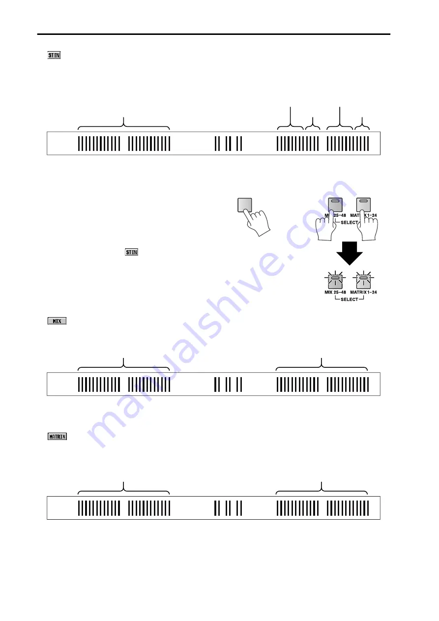
When this button is on, the twenty-four meters at the right of center will display the levels of ST IN 1–8 in the loca-
tions shown in the following diagram. While this button is on, the ST IN 1–8 levels will always be displayed in the
same location, even in FOLLOW PANEL mode.
At this time, the MIX/MATRIX bus number LED located at the bottom of the meter bridge will go dark. In the
METER section, the METER SELECT [MIX 25-48] switch and [MATRIX 1-24] switch will both blink.
By holding down the top panel [SHIFT] switch and
simultaneously pressing the METER SELECT [MIX
25-48] switch and [MATRIX 1-24] switch in the
METER section, you can also make the meter bridge
display the ST IN channel input levels. In this case,
the METER SELECT [MIX 25-48] switch and
[MATRIX 1-24] switch will simultaneously blink,
and the above-mentioned
button will automati-
cally turn on.
•
button
When this button is on, the forty-eight meters at left and right will display the output levels of MIX channels 1–48.
This button is linked with the METER section METER SELECT [MIX 25-48] switch.
At this time, the MIX/MATRIX bus number LED located at the bottom of the meter bridge will light. In the METER
section, the METER SELECT [MIX 25-48] switch will light, and the [MATRIX 1-24] switch will go dark.
•
button
When this button is on, the output levels of MIX channels 1–24 will be displayed at the left of center, and the output
levels of MATRIX channels 1–24 will be displayed at the right of center. This button is linked with the METER section
METER SELECT [MIX 25-48] switch.
At this time, the MIX/MATRIX bus number LED located at the bottom of the meter bridge will light. In the METER
section, the METER SELECT [MIX 25-48] switch will go dark, and the [MATRIX 1-24] switch will light.
Off
ST IN 1L, 1R - 4L, 4R
[Meter bridge]
ST IN 5L, 5R - 8L, 8R
Off
Off
SHIFT
+
MIX channels 1–24
MIX
channels
25–48
[Meter bridge]
MIX channels 1–24
MATRIX channels 1–24
[Meter bridge]


