

7 - 16
FI
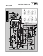
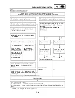
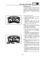
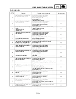
FUEL INJECTION SYSTEM
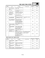
Fault code No.
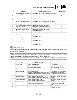
16
Symptom
Stuck throttle position sensor detected.
Used diagnostic code No. 01 (throttle position sensor)
Order
Inspection operation item and
probable cause
Operation item and countermeasure
Reinstatement
method
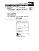
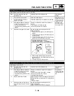
1
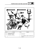
Installed condition of throttle posi-
tion sensor.
Check the installed area for looseness or pinching.
Check that it is installed in the specified position.
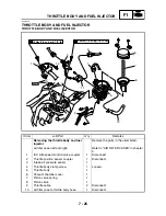
Refer to “THROTTLE BODY AND FUEL INJEC-
TOR”.
Reinstated by
starting the engine,
operating it at idle,
and then racing it.
2
Defective throttle position sensor
Execute the diagnostic mode (code No. 01)
Replace if defective.
Refer to “THROTTLE BODY AND FUEL INJEC-
TOR”.
3
When fault code No. 15 has been
detected.
Refer to “Fault code No. 15”.
Refer to “Fault
code No. 15”.
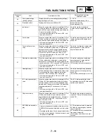
Fault code No.
19
Symptom
Open circuit in the input line of ECU (blue/yellow lead) detected.
Used diagnostic code No. 20 (sidestand switch)
Order
Inspection operation item and
probable cause
Operation item and countermeasure
Reinstatement
method
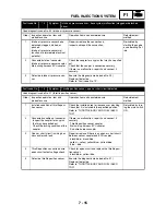
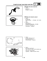
1
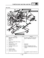
Connected state of connector
Main wiring harness ECU coupler
(blue/yellow connector)
Execute the diagnostic mode (code No. 20)
Check the coupler for any pins that may have pulled
out.
Check the locking condition of the coupler.
If there is a malfunction, repair it and connect it
securely.
Reinstated by
reconnecting the
wiring and retract-
ing the sidestand.
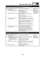
2
Open or short circuit in wiring har-
ness and/or sub lead.
Repair or replace if there is an open circuit.
Sidestand switch signal input line of ECU coupler
blue/yellow
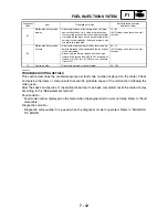
Fault code No.
21
Symptom
Coolant temperature sensor open or short circuit is detected.
Used diagnostic code No. 06 (coolant temperature sensor)
Order
Inspection operation item and
probable cause
Operation item and countermeasure
Reinstatement
method
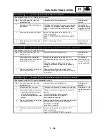
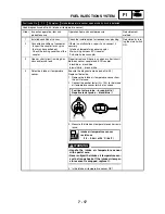
1
Installed condition of sensor
Check the installed area for looseness or pinching.
Reinstated by turn-
ing the main switch
ON.
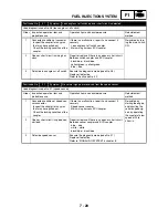
2
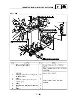
Connected condition of connector
Inspect the coupler for any pins
that may have pulled out.
Check the locking condition of the
coupler.
If there is a malfunction, repair it and connect it
securely.
Coolant temperature sensor coupler
Main wiring harness ECU coupler
Sub-wire harness coupler
3
Open or short circuit in wiring har-
ness and/or sub lead.
Repair or replace if there is an open or short circuit.
Between sensor coupler and ECU coupler
black/blue – black/blue
green/red – green/red
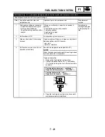
4
Defective coolant temperature sen-
sor.
Execute the diagnostic mode (code No. 06)
Replace if defective.
Refer to “COOLING SYSTEM” in chapter 8.
Содержание 2004 YP400
Страница 1: ...2004 YP400 S 5RU1 AE1 SERVICE MANUAL ...
Страница 2: ......
Страница 8: ......
Страница 9: ...GEN INFO 1 ...
Страница 11: ...GEN INFO ...
Страница 28: ...SPEC 2 ...
Страница 30: ...SPEC ...
Страница 50: ...2 20 SPEC Camshaft cap tightening sequence Cylinder head tightening sequence TIGHTENING TORQUES ...
Страница 77: ...CHK ADJ 3 ...
Страница 137: ......
Страница 138: ...CHAS 4 ...
Страница 210: ......
Страница 211: ...ENG 5 ...
Страница 286: ...COOL 6 ...
Страница 288: ...COOL ...
Страница 299: ...FI 7 ...
Страница 301: ...FI ...
Страница 342: ...ELEC 8 ...
Страница 378: ...8 34 ELEC LIGHTING SYSTEM ...
Страница 404: ......
Страница 405: ...TRBL SHTG 9 ...
Страница 415: ......
Страница 416: ...YAMAHA MOTOR CO LTD 2500 SHINGAI IWATA SHIZUOKA JAPAN ...