

7 - 11
FI
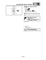
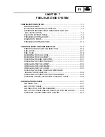
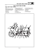
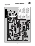
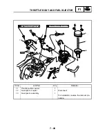
FUEL INJECTION SYSTEM
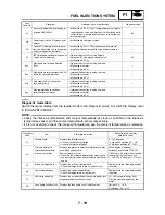
09
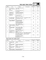
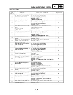
Fuel system voltage
(battery voltage)
Displays the fuel system voltage (battery voltage).
Engine stop switch is on.
0 ~ 18.7 V
Normally, approximately 12.0 V
20
Sidestand switch
Displays that the switch is ON or OFF.
Stand retracted: ON
Stand extended: OFF
30
Ignition coil
When the engine stop switch is turned from OFF to
ON, the ignition coil is actuated five times per sec-
ond and the engine trouble warning light comes on.
• Connect an ignition checker.
• If the engine stop switch is ON, turn it OFF, and
then turn it back ON.
Check that spark is generated,
5 times with the engine stop switch
ON.
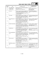
36
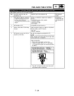
Fuel injector
When the engine stop switch is turned from OFF to
ON, the fuel injector is actuated five times per sec-
ond and the engine trouble warning light comes on.
• If the engine stop switch is ON, turn it OFF, and
then turn it back ON.
Check the operating sound of the fuel
injector five times with engine stop
switch ON.
50
Fuel injection system
relay
When the engine stop switch is turned from OFF to
ON, the fuel injection system relay is actuated five
times per second and the engine trouble warning
light comes on (the light is OFF when the relay is
ON, and the light is ON when the relay is OFF).
• If the engine stop switch is ON, turn it OFF, and
then turn it back ON.
Check the fuel injection system relay
operating sound 5 times with the
engine stop switch ON.
51
Radiator fan motor relay
When the engine stop switch is turned from OFF to
ON, the radiator fan motor relay is actuated five
times every 5 seconds and the engine trouble warn-
ing light comes on. (ON 2 seconds, OFF 3 seconds)
• If the engine stop switch is ON, turn it OFF, and
then turn it back ON.
Check the radiator fan motor relay
operating sound 5 times with the
engine stop switch ON.
(At that time, the fan motor rotates.)
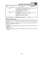
52
Headlight relay 1
When the engine stop switch is turned from OFF to
ON, the headlight relay is actuated five times every
5 seconds and the engine trouble warning light
comes on. (ON 2 seconds, OFF 3 seconds)
• If the engine stop switch is ON, turn it OFF, and
then turn it back ON.
Check the headlight relay operating
sound 5 times with the engine stop
switch ON.
(At that time, the headlight turns ON.)
54
ISC (idle speed control)
valve
When the engine stop switch is turned from OFF to
ON, the ISC (idle speed control) valve fully closes,
and then it opens until it is at the standby opening
position when the engine is started. This operation
takes approximately 12 seconds until it is com-
pleted.
• If the engine stop switch is ON, turn it OFF, and
then turn it back ON.
The ISC (idle speed control) valve
unit vibrates when the ISC (idle speed
control) valve operates.
57
Grip warmer relay
When the engine stop switch is turned from OFF to
ON, the grip warmer relay is actuated and the
engine trouble warning light comes on. (the light is
OFF when the relay is OFF, and the light is ON
when the relay is ON).
• If the engine stop switch is ON, turn it OFF, and
then turn it back ON.
Check the grip warmer relay operat-
ing sound 1 time with the engine stop
switch ON.
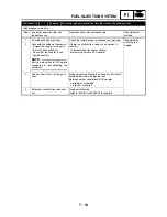
60
EEPROM fault code dis-
play
• Transmits the abnormal portion of the data in the
EEPROM that has been detected as a fault code
44.
• If multiple malfunctions have been detected, differ-
ent codes are displayed at 2-second intervals, and
this process is repeated.
01 CO adjustment value is detected.
03 Code re-registering key (immobi-
lizer) is detected.
04 Throttle valve fully closed notifica-
tion value is detected.
(00) Displays when there is no mal-
function.
Diagnostic
code
Item
Description of action
Data displayed on meter
(reference value)
Содержание 2004 YP400
Страница 1: ...2004 YP400 S 5RU1 AE1 SERVICE MANUAL ...
Страница 2: ......
Страница 8: ......
Страница 9: ...GEN INFO 1 ...
Страница 11: ...GEN INFO ...
Страница 28: ...SPEC 2 ...
Страница 30: ...SPEC ...
Страница 50: ...2 20 SPEC Camshaft cap tightening sequence Cylinder head tightening sequence TIGHTENING TORQUES ...
Страница 77: ...CHK ADJ 3 ...
Страница 137: ......
Страница 138: ...CHAS 4 ...
Страница 210: ......
Страница 211: ...ENG 5 ...
Страница 286: ...COOL 6 ...
Страница 288: ...COOL ...
Страница 299: ...FI 7 ...
Страница 301: ...FI ...
Страница 342: ...ELEC 8 ...
Страница 378: ...8 34 ELEC LIGHTING SYSTEM ...
Страница 404: ......
Страница 405: ...TRBL SHTG 9 ...
Страница 415: ......
Страница 416: ...YAMAHA MOTOR CO LTD 2500 SHINGAI IWATA SHIZUOKA JAPAN ...