Control Surface
17
DM1000 Version 2—Owner’s Manual
2
Control Sur
face & Rear Panel
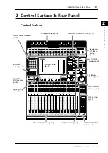
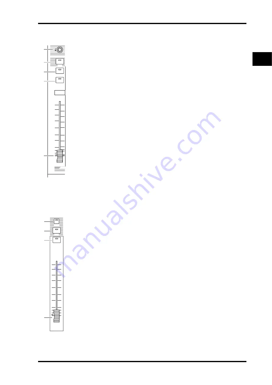
Channel Strip Section
A
Encoders 1–16
These rotary Encoders adjust the channel parameter settings. Depending on the button
selected in the ENCODER MODE section (see page 18), the Encoders will adjust the chan-
nel pan setting (when the ENCODER MODE [PAN] button indicator is lit), the AUX Send
level (when the ENCODER MODE [AUX] button indicator is lit), or any parameter (when
the ENCODER MODE [ASSIGN] button indicator is lit).
These Encoders also feature push switches that are used to view the value of the parameter
currently assigned to the Encoder, or to punch in or out during Automix recording.
B
[SEL] buttons 1–16
These buttons enable you to select desired channels. The [SEL] button indicator for the cur-
rently-selected channel lights up. The channel selected by each [SEL] button depends on the
currently-selected button in the LAYER section (see page 22).
These buttons also allow you to select channels for Automix recording and playback, create
or cancel channel pairs, and add channels to (or remove them from) Fader, Mute, EQ, and
Compressor groups.
C
[SOLO] buttons 1–16
These buttons solo the selected channels. The [SOLO] button indicator of the cur-
rently-soloed channel lights up.
D
[ON] buttons 1–16
These buttons turn the selected channels on or off. The [ON] button indicators for On
channels light up.
E
Channel faders 1–16
These are touch-sensitive 100 mm motorized faders. Depending on the button selected in
the FADER MODE Section (see page 18), the faders will adjust the input or output level of
the selected channels or buses, or adjust the AUX Send level.
STEREO Section
A
[AUTO] button
When this button is turned on, you can use the [SEL] buttons 1–16 to turn the Automix
function on or off.
B
[SEL] button
Selects the Stereo Bus.
C
[ON] button
Turns the selected bus on or off.
D
[STEREO] fader
This touch-sensitive 100 mm motorized fader adjusts the final output level of the Stereo
Bus.
0
5
10
15
20
30
40
50
60
70
50
40
30
20
15
10
+10
5
0
5
ON
SOLO
SEL
AUX
1
1
1
17
33
1
2
3
4
5
AUTO
ON
SEL
STEREO
70
60
50
40
30
20
15
10
5
0
1
2
3
4
Содержание 006IPTO-F0
Страница 42: ...42 Chapter 3 Operating Basics DM1000 Version 2 Owner s Manual ...
Страница 52: ...52 Chapter 4 Connections and Setup DM1000 Version 2 Owner s Manual ...
Страница 92: ...92 Chapter 7 Bus Outs DM1000 Version 2 Owner s Manual ...
Страница 108: ...108 Chapter 8 Aux Sends DM1000 Version 2 Owner s Manual ...
Страница 146: ...146 Chapter 11 Surround Functions DM1000 Version 2 Owner s Manual ...
Страница 214: ...214 Chapter 16 Automix DM1000 Version 2 Owner s Manual ...
Страница 385: ...DM1000 Block Diagram ...

