Seite 80 von 170 Artikel Nr.: 1080622001 Stand: 2022_06_24 Technische Änderungen und Irrtümer vorbehalten.
communications are possible. If read-outs are carried out more rarely, the possible number of communications will increase.
7.2
Retrofitting with an additional communication interface
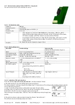
To our calculator further communication interfaces can be added later. You will find the description of our optional interfaces
in the operating instructions „Communication Interfaces POLLUSTAT(C)“.
During installation of the retrofitting module observe the ESD requirements according to EN 61340-5-1.
This means that on location an antistatic wrist strap with an integrated 1 MΩ resistor has to be used which must be connected
to a proper spot: This is either a grounded pipe or – only with an appropriate adapter! – a Schuko plug grounding socket. The
antistatic wrist strap must be worn tightly on the skin of the wrist.
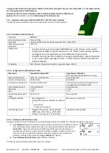
Open the calculator by pulling the clamping bracket at the upper housing´s leading edge up.
Plug the interface module on the right side of the PC board. If there are module cables you have to loosen the needed number
of cable glands and to glide them over the cables. Remove the blind plugs from the cable gland openings and feed the cables
into the calculator.
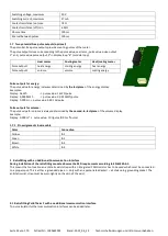
Protect the calculator against unauthorized opening using one of the numbered adhesive seals enclosed to the modules. The
added bar code label can be used for the purpose of documentation.
7.3
Exchanging the battery
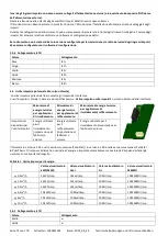
The calculator´s battery is easy to exchange by authorized technical personnel (our
replacements only). Replaced batteries must be disposed of according to relevant
environmental regulations.
Open the calculator by pulling the clamping bracket at the upper housing´s leading
edge up. Afterwards protect the calculator against unauthorized opening using one of
the numbered adhesive seals enclosed to the batteries (stick it upon the seal
destroyed). The added bar code label can be used for the purpose of documentation.
7.4
Optional power pack
The equipment of an external 24V or 230V power supply is possible. For all details on retrofitting and operation, please refer to
the operating and assembly instructions enclosed with the power supply unit.
8
Display
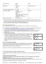
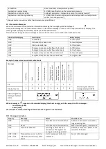
The calculator has a liquid crystal display with 8 digits and special characters. The values that can be shown are divided into five
display loops. All data is retrieved using the push-button next to the display.
At the start you are automatically in the main loop (1st level). By pressing the push-button longer than 4 seconds you change
to the next display loop. Keep the push-button pressed until you reach the desired information loop. By pressing the push-
button briefly each time you can scan all the information within a loop.
After 2 minutes of non-use of the push-button, the display will automatically be deactivated.
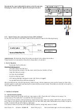
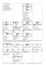
Level 1 / Main Loop:
2) Segment test on / off
(all segments triggered
simultaneously)
4) Total flow volume in m³


