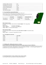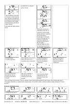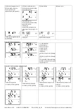
Seite 93 von 170 Artikel Nr.: 1080622001 Stand: 2022_06_24 Technische Änderungen und Irrtümer vorbehalten.
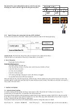
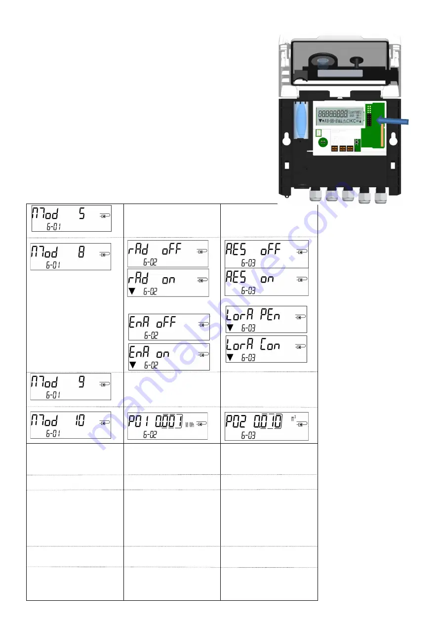
Open the calculator by pulling the clamping bracket at the upper housing´s
leading edge up.
Plug the interface module on the right side of the PC board. If there are module
cables you have to loosen the needed number of cable glands and to glide them
over the cables. Remove the blind plugs from the cable gland openings and feed
the cables into the calculator.
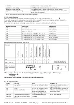
Protect the calculator against unauthorized opening using one of the numbered
adhesive seals enclosed to the modules (stick it upon the seal destroyed). The
added bar code label can be used for the purpose of documentation.
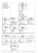
3 Display in the Module Loop (Optional)
Level 6 / Module Loop:
1) Display of plugged
module (alternatively):
5 = 1 pulse output;
8 = wireless M-Bus + 3 pulse
inputs;
9 = M-Bus + 3 pulse inputs;
10 = 2 pulse outputs
or:
2) Display depending on
plugged module and setup:
wireless M-Bus (radio) off/
wireless M-Bus (radio) on;
LoRa on/ LoRa off;
pulse value /
pulse output 1
or:
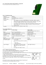
3) Display depending on
plugged module and setup:
radio encryption (AES) off;
radio encryption (AES) on;
LoRa pending/
LoRa connected
pulse value /
pulse output 2

