Seite 85 von 170 Artikel Nr.: 1080622001 Stand: 2022_06_24 Technische Änderungen und Irrtümer vorbehalten.
Operating Instructions
Communication Interfaces PolluStat & PolluTherm F
1
Interfaces and Options
1.1
Optical (infrared) interface
For communication with the optical interface an optocoupler and a suitable configuration software are necessary. The
optocoupler and the configuration software are available as accessory equipment.
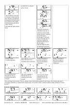
The optical infrared interface will be activated by automatically sending a header (according to EN 13757-3). Baud rate: 2400
baud.
Then you can communicate with the meter for 4 seconds. After every valid communication the meter is open for another 4
seconds. Afterwards the display is deactivated.
The number of read-outs per day via the optical interface is limited. During daily read-out at least 4 communications are
possible. If read-outs are carried out more rarely, the possible number of communications will increase.
1.2
M-Bus (optional)
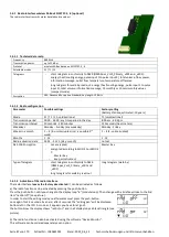
The M-Bus is a galvanically isolated interface for the transmission of meter data (absolute
values).
General information about the M-Bus interface:
It is important to note that the acknowledged state of the art technology rules and the
relevant legal restraints (international and local; see “Relevant Norms / Standards /
Literature M-Bus”) are to be observed.
The installation has to be performed by authorized, skilled persons.
If the regulations and the information in the installation and operating instruction manuals
are not strictly followed, or if the installation is shown to be faulty, any resulting expenses
will be charged to the company responsible for the installation.
Recommended type of cable: Telephone cable J-Y(ST)Y 2x2x0.8mm².
It is important to make sure that the topology of the M-Bus network (cable lengths and cross-sections) is suitable for the
baud
rate (2400 Bd)
of the end instruments.
1.2.1 Relevant norms / standards / literature M-Bus
IEC 60364-4-41 (2005-12)
Low-voltage electrical installations - Part 4-41: Protection for safety - Protection
against electric shock
IEC 60364-4-44 (2007-08)
Low-voltage electrical installations - Part 4-44: Protection for safety - Protection
against voltage disturbances and electromagnetic disturbances
IEC 60364-5-51 (2005-04)
Electrical installations of buildings - Part 5-51: Selection and erection of electrical
equipment - Common rules
IEC 60364-5-54 (2011-03)
Low-voltage electrical installations - Part 5-54: Selection and erection of electrical
equipment - Earthing arrangements and protective conductors
EN 50310 (2011)
Application of equipotential bonding and earthing in buildings with information
technology equipment
EN 13757-1_2015, -2_2004, -
3_2013
Communication systems for meters and remote reading of meters
The M-Bus
A Documentation, Version 4.8, M-Bus User group
1.2.2 Additional technical specifications
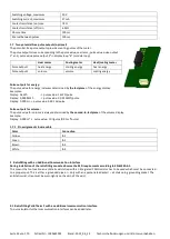
The installation has to fulfill the requirements of the relevant norms / standards / literature (see paragraph 2.1) and the
specifications as follows:
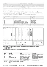
Maximum voltage M-Bus
42 V
Minimum voltage M-Bus
24 V
Maximum ripple voltage
200 mV; EN 13757-2_2004; 4.3.3.6
Maximum voltage potential
differences
2 V

