Seite 78 von 170 Artikel Nr.: 1080622001 Stand: 2022_06_24 Technische Änderungen und Irrtümer vorbehalten.
-
Sensor cables that are too long should not be rolled up tightly into an ‘air-core coil’. The cables should either be laid
out disordered, or rolled up loosely into a wide coil which can be turned and tied into an ‘8’.
Mounting
-
Loosen the two cable glands without blind plugs and glide them over the sensor cables.
-
Feed the temperature sensors through the appropriate openings of the cable glands into the terminal box.
-
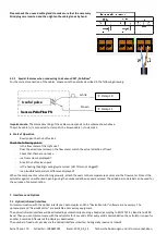
Clamp the wires (see identification label temperature sensors) as shown in the illustration:
The inlet flow temperature sensor must always be connected to clamp 5 and 6 (inlet).
The outlet flow temperature sensor must always be connected to clamp 7 and 8 (outlet).
The color of the wires does not matter.
-
Check that the connections are tight.
-
Screw the cable glands tight by hand.
5.2
Mounting the flow meter
The pulse output of the flow meter to be connected to the calculator must be identical to the calculator input pulse value.
Check the technical data of the flow meter and compare it to the specifications on the calculator.
Mounting
-
Loosen the middle cable gland and glide it over the flow meter cable.
-
Remove the blind plug in the cable gland opening. Feed the pulse cable of the flow meter through the opening into
the terminal box.
-
Clamp 10 and 11 are used for the connection to the flow meter.
-
Clamp on the wires as shown in the illustration.
Note:
For flow meters with open collector connections (electronic outputs) make sure the polarity is correct.
-
Check that the connections are tight.
-
Screw the cable gland tight by hand.


