Operation Manual
37
Chapter Description
Load Capacity Charts
Load Capacity Charts are located on the left side of the front
control panel. Load Capacity Charts are provided to assist the
operator in determining how to safely handle loads with the
forklift, including boom angle, height, and reach.
Figure 29. Load Capacity Charts
Figure 30. Hydraulic Oil Temperature, Low Brake Pressure,
and Rear Axle Lock Indicators
Hydraulic Oil Temperature Indicator
The Hydraulic Oil Temperature Indicator illuminates when the
oil temperature is above 180°F. If the Hydraulic Oil Tempera-
ture Indicator illuminates, stop and idle the engine to allow
time for cooling. If the Hydraulic Oil Temperature Indicator
does not go out after five (5) minutes, stop the forklift, follow
proper shut down procedures, tag the forklift with “Do Not
Operate” tags, and have a qualified mechanic service or repair
the forklift
BEFORE
placing it into service again.
Low Brake Pressure Indicator
The Low Brake Pressure indicator illuminates if the hydraulic
brake oil pressure gets low. If the Low Brake Pressure Indicator
is illuminated, do not release parking brake or engage
transmission until light is out. If the light does not go out,
stop the forklift, follow proper shut down procedures, tag
the forklift with “Do Not Operate” tags, and have a qualified
mechanic service or repair the forklift
BEFORE
placing it into
service again.
Rear Axle Lock Indicator
The Rear Axle Lock Indicator illuminates when the forklift is in
the axle lock mode. The rear axle locks when the parking brake
is set to ON (engaged), or the transmission is in NEUTRAL or
the service brake is applied, and when the boom is above 10°.
If the Rear Axle Lock Indicator does not illuminate, stop the
forklift, follow proper shut down procedures, tag the forklift
with “Do Not Operate” tags, and have a qualified mechanic
service or repair the forklift
BEFORE
placing it into service
again.
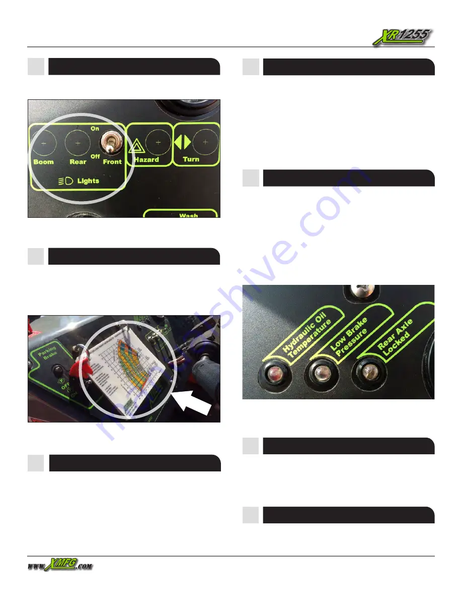
Light Switches
The Light Switches control the boom and cab lights.
Figure 28. Light Switches
Engine Warning Indicator
The forklifts equipped with the Perkins 1204 Tier 4i engines
contain systems to reduce exhaust emissions. This section
deals with the indicators and operating procedures for these
tier 4 interim systems.
Engine Warning Indicator
The Engine Warning Indicator illuminates for 5 seconds when
the key switch is moved to the RUN position. After that period,
Содержание XR1255
Страница 1: ...Operation and Safety Manual PN 24907 000 02 Perkins 1204 Tier 4 Interim ...
Страница 22: ...Operation Manual 22 Labels 7 18015 001 8 18016 001 11 18018 002 12 18019 001 9 18017 001 10 18018 001 ...
Страница 23: ...Operation Manual 23 Labels 13 18020 001 14 18021 001 17 18025 001 18 18026 001 15 18022 001 16 18023 001 ...
Страница 26: ...Operation Manual 26 Labels 31 18082 001 32 18083 001 34 18090 001 35 18300 001 36 18312 000 33 18086 002 ...
Страница 27: ...Operation Manual 27 Labels 37 18315 000 38 18043 000 39 18044 000 40 18046 000 41 18047 000 42 18048 000 ...
Страница 75: ...Lockout Tagout Operation Manual 75 Do Not Operate Tags ...
Страница 82: ...8350 EASTGATE ROAD HENDERSON NV 89015 702 636 2969 800 497 1704 www XMFG com PN 24907 000 02 ...


