1 2
3
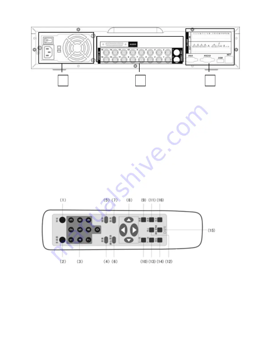
Serial number
1 Power
button
Power outlet
Fan
Figure 3-2
2
RS485 port RS232 port VGA port , USB, Network
port(RS45)
3
Audio 25-pin connection port
Video input and output port(1/2 main/assistant)
Note:
When you use Ethernet connection, use crossover cable to connect with network
card, use straight-through cable to connect PC via switch or hub.
3.4 Remote Control
The remote control is shown as in Figure 3-3.
Figure 3-3 Remote control
Serial number
Function
1 remote
switch
2 Multiple-window
switch
3
0-9 number key
4 Record
5 Auxiliary
key
6
Confirm /menu key
7 Cancel
8 Direction
key
23


