background image

4  DVR Basic Operation


Before operation, please make sure you have properly installed HDD and all the 
cable connections are right. 


4.1   Login/Logout/Main Menu 


4.1.1 Login


When system boots up, default video output is in multiple-window mode. 
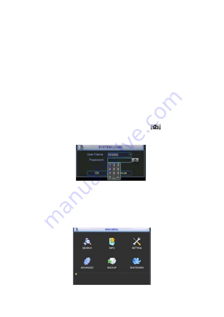
Click Enter or left click mouse, you can see the login interface. See 

Figure 4-1

System consists of four accounts: 


Username: admin.  Password: admin. 


Username: 888888. Password: 888888 


Username: 666666. Passwords: 666666(Lower user who can only monitor, 
playback, backup and etc.) 


Username: default. Password: default(hidden user) 

For security reasons, please modify you password after first login. 
Please note five times login failure within thirty minutes will result in account lock. 

About input method: Please use remote control to input. Click 


to switch 

between numeral, English character (small/capitalized) and denotation. 


4.1.2 Main 

menu


Figure 4-1 

When you login, the system main menu is shown as below. See Figure 4-2. 
There are totally six icons: search, information, setting, backup, advanced and 
shutdown. 
Move the cursor to highlight the icon, then double click mouse to enter the sub-menu. 


Figure 4-2 


26 

Содержание DVR-1670C

Страница 1: ...DVR 1670C Digital video net recorder User s Manual 1...

Страница 2: ...t CD Burner 13 2 2 5 External Power Supply Connection 13 2 2 6 Install DVR in the Machine Cabinet 13 2 3 Video and Audio Connection 13 2 3 1 Video Input Connection 13 2 3 2 Audio Input 14 2 3 3 Audio...

Страница 3: ...4 3 2 Basic operation 30 4 3 3 File backup during search operation 31 4 3 4 Backup in search interface 32 4 3 5 Calendar 32 4 4 Record Setup Schedule 33 4 4 1 Go to schedule interface 33 4 4 2 Basic O...

Страница 4: ...47 5 3 System setting 48 5 3 1 General 48 5 3 2 Encode 49 5 3 3 Schedule 50 5 3 4 RS232 50 5 3 5 Network 50 5 3 6 Alarm 52 5 3 7 Detect 52 5 3 8 Pan Tilt Zoom 52 5 3 9 Display 52 5 3 10 Default 53 5 4...

Страница 5: ...ork connection 69 7 2 Login and logout 69 7 3 Go to real time monitor mode 70 7 4 Video Right mouse menu operation 70 7 4 1 Real time Monitor 71 7 4 2 Multi camera Preview 71 7 4 3 Start Dialog 71 7 4...

Страница 6: ...some series DVR 89 7 7 11 About 89 7 8 Un install web control 89 8 SERIAL PORT OPERATION 90 8 1 Network Connection 90 8 2 Keyboard 90 8 3 Matrix Connection 90 9 FAQ 91 Welcome Thank you for purchasing...

Страница 7: ...cal safety codes We assume no liability or responsibility for all the fires or electrical shock caused by improper handling or installation 2Transportation security Heavy stress violent vibration or w...

Страница 8: ...ld be installed in a cool dry place away from direct sunlight inflammable explosive substances and etc 6 Accessories Be sure to use all the accessories recommended by manufacturer Before installation...

Страница 9: ...D RW network download Alarm triggering screen tips buzzer PTZ preset e mail FTP upload Smart HDDs Management non working HDD hibernation HDD faulty alarm Raid function Powerful network software built...

Страница 10: ...30K Audio Output 1 channel BNC 200 3000mv 5K Audio Compression ADPCM Video Detection Alarm Motion Detection Zones 192 16 12 detection zones Sensitivity 1 6 level 6 is highest Trigger recording PTZ mov...

Страница 11: ...DVD RW built in IDE Burner network download Network Interface RJ 45 Port 10 100M Network Functions TCP IP DHCP DDNS PPPOE E mail FTP Remote operation Monitor PTZ control playback system setting file...

Страница 12: ...u ask for our service after sales 2 1 3Check after opening the front cover Besides checking apparent damages please check whether there is any loose connection between the front panel s data ribbon po...

Страница 13: ...Supply Connection Please check input voltage and device power button do match or not We recommend you use UPS to guarantee steady operation DVR life span and other peripheral equipments operation such...

Страница 14: ...le for various complicated surrounding When you use pc type monitor to replace the industrial monitor Please note To defer aging do not open for a long time Regular demagnetization will facilitate the...

Страница 15: ...to connect to the grounding Avoid the entry of high voltage Ensure proper wiring and some thunder protection measures For long signal wires 120 should be parallel connected between A B lines on the f...

Страница 16: ...a lot of pan tilt decoders you should parallel connect 120 between A B lines e is ground cable Please refer to Figure 2 3 Figure 2 2 4 8 16 ch grounding alarm inputs Normal open or Normal close type...

Страница 17: ...al 200 103 times 0 5Hz Temperature 40 70 2 5 Record Modes Selection and Configuration This series DVR can provide multiple recording modes You can select and configure as you needed To get the best ba...

Страница 18: ...bandwidth access mode when you connect in WAN Ethernet cable should be made according to your local standard Note Please apply this manual to the right models Do not use this manual to install or oper...

Страница 19: ...DVR 2 Remove the HDD bracket from internal unit 3 4 3 Dismantle the upper HDD bracket 4 Install the HDD Note the HDD is placed upside down Please make sure bracket is in correct position master 5 sla...

Страница 20: ...ront panel S N Name Icon Function 1 Power button POWER Power button press for three seconds to shut down DVR Power indication light Power indication light 2 Shift In preview interface no other menu pr...

Страница 21: ...ral keys Slow play Multiple slow play speeds or normal playback One window monitor mode click this button to display assistant functio PTZ control and image color In PTZ menu shift PTZ control menu As...

Страница 22: ...te control Function indication light 7 Window switch MULT Switch between one window and multiple window display modes Enter ENTER confirm current operation go to default button Go to main menu Cancel...

Страница 23: ...ant Note When you use Ethernet connection use crossover cable to connect with network card use straight through cable to connect PC via switch or hub 3 4Remote Control The remote control is shown as i...

Страница 24: ...ter to small character X delete all confirm the current value and close current panel Implement current selection such as double click one file name to playback the video Surveillance mode In single m...

Страница 25: ...pops up on the right Click that button to switch between numeral input and English input capitalized and small Use or to shift between small character and capitalized character 3 6 2 Front Panel Fron...

Страница 26: ...o can only monitor playback backup and etc Username default Password default hidden user For security reasons please modify you password after first login Please note five times login failure within t...

Страница 27: ...king status after power failure 4 1 5 Replace button battery Please always use the same type battery and check system time regularly We recommend replace battery regularly such as one year to guarante...

Страница 28: ...iority After manual setup all selected channels will begin ordinary recording Schedule channel records as you have set in recording setup Main Menu Setting Schedule Stop all channels stop recording No...

Страница 29: ...ystem is in manual recording all scheduled set up you have set in will be null Main menu Setting Schedule The indicator light in front panel will turn on system begins manual record now See Figure 4 8...

Страница 30: ...M motion detection recording file There are two display modes 1p one window playback 2p two window playback Figure 4 10 Please refer to the following sheet for more information Serial number Function...

Страница 31: ...n System supports backup operation during search You can draw a before file name multiple choices Then click backup button Button 14 in Figure 4 10 4 3 3 1 Slow playback and fast playback Please refer...

Страница 32: ...kward play in playback interface In normal playback mode left click backward play button system begins backward playback Double click backward play button again system goes to pause mode When system i...

Страница 33: ...n A Alarm 4 4 2 Basic Operation Figure 4 12 There are totally six periods See Figure 4 12 Channel Please select the channel number first You can select all if you want to set for the whole channels We...

Страница 34: ...occurred in one disk there is a spare one in the other disk You can use this function to maintain data reliability and safety 4 4 2 2 1 Redundant Backup Setup In the main menu from setting to schedule...

Страница 35: ...n item Record channel select the channel to activate recording function once alarm occurred Please make sure you have set MD record in encode interface Main Menu Setting Schedule and schedule record i...

Страница 36: ...n Click Fn to switch between deployment and withdraw motion detection After setting click enter button to exit Figure 4 14 Figure 4 15 4 5 3 Video loss Figure 4 16 In Figure 4 14 select video loss You...

Страница 37: ...sk lens system can alarm you to guarantee video continuity Camera mask detection interface is shown as in Figure 4 18 Channel select the channel you want to enable camera mask detection function Type...

Страница 38: ...ect proper channel to record alarm video Multiple choices At the same time you need to set alarm record in schedule interface Main Menu Setting Schedule and select schedule record in manual record int...

Страница 39: ...ckup device and then channel file start time and end time Click add button system begins search All matched files are listed below System auto calculates the capacity needed and remained See Figure 4...

Страница 40: ...ackup process Note When you click stop button during the burning process there are two conditions for different devices For CD ROM device the stop function becomes activated immediately and there is n...

Страница 41: ...9 PTZ Setup Figure 4 23 Note The camera video should be in the current screen Before setup please check the following connections are right PTZ and decoder connection is right Decoder address setup is...

Страница 42: ...ton in the front panel or click Fn key in the remote control The image is shown as in Figure 4 25 Figure 4 25 Click Pan Tilt Zoom the image is shown as below See Figure 4 26 Here you can set the follo...

Страница 43: ...ion size It can realize PTZ automatically We usually call it 3D intelligent positioning Here is a sheet for you reference Figure 4 28 Name Function key function Shortcut key Function key function Shor...

Страница 44: ...osition In Figure 4 29 click preset button and input preset number The image is shown as in Figure 4 31 Add this preset to one patrol tour 4 10 2 Activate Preset Figure 4 31 In Figure 4 30 please inpu...

Страница 45: ...d iris Go back to Figure 4 33 and click end button You can memorize all these operations as pattern 1 4 10 6 Activate Pattern Function Figure 4 33 In Figure 4 30 input mode value in the No blank and c...

Страница 46: ...utton changes to stop button Click stop button to terminate scan operation 4 11 Dome Menu Control In Figure 4 30 click page switch button the image is shown as below See Figure 4 35 Click menu to ente...

Страница 47: ...wn as below 5 2Main menu When you login the system main menu shows as below See Figure 5 1 There are totally six icons search Information setting backup advanced and shutdown Move the cursor to highli...

Страница 48: ...ese French Spanish All languages listed here are optional Slight difference maybe found in various series HDD full Here is for you to select working mode when hard disk is full There are two options s...

Страница 49: ...st image quality Frame rate there are six levels 1 f s 2f s 3f s 6f s 12f s 25f s Some series DVRs only support PAL 25f s Enable audio you can turn on or off the audio Cover area Privacy mask Here is...

Страница 50: ...op bit There are three values 1 1 5 2 Parity there are three choices none odd even After all the setups please click save button system goes back to the previous menu Figure 5 5 RS232 5 3 5 Network He...

Страница 51: ...5 7 5 3 5 1 PPPoE Connection Set PPPOE as on and then please input PPPoE name and PPPoE password you get from your ISP Internet service provider After saving it you need to restart to active your con...

Страница 52: ...Pan Tilt Zoom The pan tilt zoom setup includes the following items Please select channel first See Figure 5 8 Protocol select corresponding PTZ protocol Address input corresponding PTZ address Baud ra...

Страница 53: ...ction View1 4 9 16 System support 1 4 9 16 window tour Please highlight icon to select the corresponding function After all the setups please click save button system goes back to the previous menu 5...

Страница 54: ...anual record account auto maintain and TV adjust Figure 5 11 Advanced 5 5 1 Hard disk management Here is for you to view and implement hard disk management See Figure 5 12 You can set proper mode for...

Страница 55: ...o 6 Delay value is from 0 to 240 seconds Please note when HDD capacity is not full system only alarms once After all the setups please click OK button system goes back to the previous menu 5 5 2 Alarm...

Страница 56: ...nt For group or user management there are two levels admin and user The user name and group name can consist of eight bytes One name can only be used once There are four default user admin 888888 6666...

Страница 57: ...ve button system goes back to the previous menu Figure 5 17 Auto maintain 5 5 7 TV adjust Here is for you to adjust TV output setup See Figure 5 18 Please drag slide bar to adjust After all the setups...

Страница 58: ...d to build TV walls and tour and display the cameras one by one 5 5 8 3 Rear Panel Connection The rear panel is shown as below See Figure 5 19 Figure 5 19 rear panel 5 5 8 4 37 pin cable introduction...

Страница 59: ...e Figure 5 22 Figure 5 22 Right mouse menu 5 5 8 6 Video Matrix Interface and Application The video matrix window is shown as in Figure 5 23 Now it support 4 channel matrix outputs You can set for eac...

Страница 60: ...t the alarm in channel number from the drawdown menu If there is an alarm signal from the channel selected the matrix output will go to tour as you set in the Alarm setting Setting alarm See Figure 5...

Страница 61: ...output one begins touring between CAM1 CAM3 and CAM4 of the DVR until alarm activation tour stops Figure 5 26 Example two 5 6Information Here is for you to view system information There are totally f...

Страница 62: ...ime is the same or not Please go to setting then general to modify system time At last reboot the system to solve this problem In IDE information column means OKX means error occurred means there is n...

Страница 63: ...wing information See Figure 5 30 5 6 4 Version Figure 5 30 Log Here is for you to view some version information See Figure 5 31 Channel Alarm in Alarm out System version Baud rate Start upgrade 5 6 5...

Страница 64: ...ine users Double click exit button system pop up a dialogue box for you to select See Figure 5 33 Logout menu user log out menu You need to input password when you login the next time Restart applicat...

Страница 65: ...s Iris Click icon and to adjust zoom focus and Iris Figure 6 2 Zoom Focus Iris setup In Figure 6 2 please click direction arrows See Figure 6 3 to adjust PTZ position There are totally eight direction...

Страница 66: ...atrol pattern border function In Figure 6 2 click the set button The image shows as below Here you can set the following items Preset Patrol Pattern Border Figure 6 5 Preset patrol pattern border setu...

Страница 67: ...gure 6 6 please input preset number in the No blank and click preset button 6 2 3 Patrol setup In Figure 6 5 click patrol button The image shows like Figure 6 8 Input preset number and then add this p...

Страница 68: ...Repeat the above procedures to set right limit Figure 6 10 border setup 6 2 8 Activate border function In Figure 6 6 click auto scan button the system begins auto scan Correspondingly the auto scan b...

Страница 69: ...pen IE and input DVR address in the address column For example if your DVR IP is 10 1 27 200 then please input http 10 1 27 200 in IE address column System pops up warning information to ask you wheth...

Страница 70: ...u want to view Start dialogue click here to begin audio talk Multi camera preview System supports various video preview modes Decode quality there are totally four levels general good better and best...

Страница 71: ...ayback bar when you are viewing video file See Figure 7 6 Record Stop Snapshoot Full screen Close Figure 7 6 7 4 6 PTZ control Please click the corresponding direction arrow to adjust zoom focus and i...

Страница 72: ...TZ set button You can see the following dialogue box See Figure 7 9 You can select in the dropdown list Figure 7 9 7 4 7 Volume Adjustment Please drag volume bar to adjust audio level You can draw a b...

Страница 73: ...s to double click on the current monitor window directly the other is to select Full screen in the right click menu items During multi window state choose one of the windows and double click for full...

Страница 74: ...ew the search results Double click file name you can view the file and system will automatically backup the image in you installation directory Figure 7 15 In the search result interface you can selec...

Страница 75: ...nd then click down load button System pops up a dialogue box asking you specify directory See Figure 7 17 Figure 7 17 Then you can input file name and click save to backup file in your local pc During...

Страница 76: ...s dav For example file name a 0120021205071028 mp4 means 01 channel 1 20021205 5th December 2002 071028 7 o clock 10 minutes 28 seconds 7 6System settings Click configure button there are totally seve...

Страница 77: ...configuration to a directory The file extension name is CFG See Figure 7 20 7 6 1 2 Load configuration Figure 7 20 Click import configuration button in Figure 7 19 You can draw a before checkbox to l...

Страница 78: ...p recording when disk is full You can select channel number protocol address and baud rate to control the lens or PTZ Figure 7 22 7 6 3 Schedule Click schedule button the system is shown as below See...

Страница 79: ...BR Quality There are six levels The different data flux occupies different bandwidth and the transmission image qualities are also different Among them level 6 needs the widest bandwidth and can revea...

Страница 80: ...o choose record channel and output port See Figure 7 25 There are two alarm types normal open or normal close Delay time ranges from 10 to 300 seconds You can draw a before the check box to enable rec...

Страница 81: ...motion detection area Click Full screen or right click mouse to view the motion detection area in full screen After setting the area you can Save channel or Clear the area Alarm outputHere you can en...

Страница 82: ...ware running in this PC In other words this PC is a DNS domain name server In network DDNS input your PPPoE name you get from you IPS and server IP PC with DDNS Click save and then reboot system Click...

Страница 83: ...Click assistant setting the image shows as below See Figure 7 30 There are nine function keys Please note Matrix control item only applies for some special series 7 7 1 User Manage Figure 7 30 Here i...

Страница 84: ...2 Delete Group Figure 7 32 Click Delete Group the image is shown as in Figure 7 33 Note You can only delete empty group E g There is no user in current group 7 7 1 3 Modify Group Figure 7 33 Click mo...

Страница 85: ...uch as in Figure 7 32 Figure 7 35 click power button the image is shown as in Figure 7 36 Here is for you to set user s power There are three power groups main control power monitor power playback pow...

Страница 86: ...s below See Figure 7 39 You can select mode for each channel 7 7 3 Log information Figure 7 39 Systems automatically backup all operation in log information You can click this button to view in detail...

Страница 87: ...ation of the system See Figure 7 42 Here you can Turn on off audio Select video type Select preview image Preview image Close or open auto tour monitoring View network data flux 7 7 6 Alarm Prompt Fig...

Страница 88: ...y channel name in DVR end this modification not applies to web end or standalone end you need to use this interface to refresh 7 7 8 Upgrade BIOS Figure 7 44 Click upgrade BIOS button the image is sho...

Страница 89: ...re 7 47 7 7 11 About Figure 7 47 Here is for you to view basic system information See Figure 7 48 Figure 7 48 7 8Un install web control There are three ways for you to un install web control From star...

Страница 90: ...ch as protocol Connect DVR RS232 port to shifter 25 pin RS232 port and then set proper control addresses for all connected DVRs Now you can input DVR control address and use keyboard keys to set menu...

Страница 91: ...ry and clean Keep ventilation openings smooth Otherwise it will reduce system stability and lifelong 6 I can not see video signal on one channel while the other channels are ok Check the video cable c...

Страница 92: ...e seconds this phenomena is normal 12 What peripheral equipment DVR can work with DVR supports much peripheral equipment such as keyboardmatrixcontrol decode card alarm input and output equipmentalarm...

Отзывы: