28
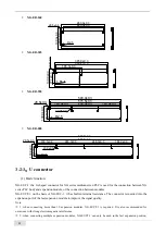
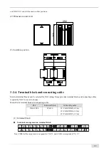
Connect the power module, XG main body and XG expansion module to the guide rail through U-connector,
and fix them with bottom screws. The installation steps are as follows:
①
Insert the L Port of the U-shaped connector into the
left interface on the back of the PLC body (right side in
front view)
②
Hang the installation hook on the upper side of the
PLC body to the upper side of the installation guide rail
according to the direction shown in the figure
③
Fix the PLC to the mounting rail as shown in the
figure below
④
Please fix the screw hole below the PLC with screws
⑤
Plug the L Port of the U-connector into the left
interface on the back of the expansion module 1 (right
side in front view)
⑥
Hang the installation hook on the upper side of the
#1 module to the upper side of the installation guide
rail according to the direction shown in the figure. The
expansion port on the left side of the module is
connected to the R port of the U-connector on the main
body
⑦
Please fix the screw hole under the module 1 with
screws
⑧
Continue to install the following modules in the
same way, and the effect is shown in the following
figure.
Note:
※
1: if the power module XG-P75-E is selected, please install the power module on the left side of the PLC body
according to the installation steps
①
~
④
.
※
2: the R port on the back of the last expansion module does not need to be installed with a U-connector.
Содержание XG Series
Страница 1: ...1 XG series PLC User manual Hardware Wuxi Xinje Electric Co Ltd Data No PG01 20210906EN 3 6...
Страница 8: ......
Страница 26: ...18 The LAN2 port of XG2 series is used for EtherCAT bus synchronous control of 32 axis motor...
Страница 55: ...47...

