10
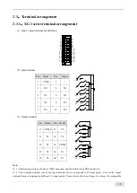
Note: When the dial switches SW1 and SW2 are used for RS485 communication, whether the PLC is the terminal.
When the PLC is at the beginning or end of the bus, please turn the dial switch to on.
1-3-2
.
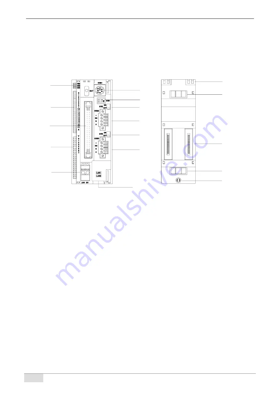
XG2 series structural composition
(13)
(14)
(15)
(14)
(16)
(2)
(4)
(3)
(1)
(6)
(7)
(8)
(9)
(10)
(11)
(12)
(5)
Note:
※
1: when the dial switches SW2 and SW3 are used for RS485 communication, whether the PLC is the terminal.
When the PLC is at the beginning or end of the bus, please turn the dial switch to on.
※
2: input and output wiring needs to be used with external terminal blocks and adaptive connecting cables. See
section 5-1 for details.
(1): System indicator
PWR: power LED
RUN: run LED
ERR: error LED
(2): Input labels and indicator
(3): I/O terminals
(4): Output labels and indicator
(5): Power supply input
(6): RS232 port (COM1)
(7): PLC updating dial switch
(8): RS485 port (COM2) dial switch
(9): RS485 port (COM2)
(10): RS485 port (COM3) dial switch
(11): RS485 port (COM3)
(12): RJ45 port (LAN1, LAN2)
(13): Mounting hook
(14): Grounding metal sheet
(15): Expansion module interface
(16): Mounting hole
Содержание XG Series
Страница 1: ...1 XG series PLC User manual Hardware Wuxi Xinje Electric Co Ltd Data No PG01 20210906EN 3 6...
Страница 8: ......
Страница 26: ...18 The LAN2 port of XG2 series is used for EtherCAT bus synchronous control of 32 axis motor...
Страница 55: ...47...


