


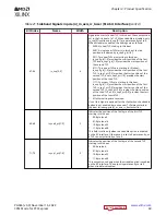


Table 21: Sideband Signals in pcie(n)_m_axis_rc_tuser (512-bit Interface) (cont'd)
Bit Index
Name
Width
Description
67:64
is_sop[3:0]
4
Signals the start of a new TLP in this beat. These outputs are
set in the first beat of a TLP. When straddle is disabled, only
is_sop[0] is valid and is_sop[3:1] are permanently set to 0.
When straddle is enabled, the settings are as follows:
•
0000: No new TLP starting in this beat.
•
0001: A single new TLP starts in this beat. ts start
position is indicated by is_sop0_ptr[1:0].
•
0011: Two new TLPs are starting in this beat.
is_sop0_ptr[1:0] provides the start position of the first
TLP and is_sop1_ptr[1:0] provides the start position of
the second TLP.
•
0111: Three new TLPs are starting in this beat.
is_sop0_ptr[1:0] provides the start position of the first
TLP, is_sop1_ptr[1:0] provides the start position of the
second TLP, and is_sop2_ptr[1:0] provides the start
position of the third TLP.
•
1111: Four new TLPs are starting in this beat.
is_sop0_ptr[1:0] provides the start position of the first
TLP, is_sop1_ptr[1:0] provides the start position of the
second TLP, is_sop2_ptr[1:0] provides the start position
of the third TLP, and is_sop3_ptr[1:0] provides the start
position of the fourth TLP.
•
All other settings are reserved.
Use of this signal is optional for the client when the straddle
option is not enabled, because a new TLP always starts in
the beat following pcie(n)_m_axis_rc_tlast assertion.
69:68
is_sop0_ptr[1:0]
2
Indicates the position of the first byte of the first TLP
starting in this beat:
•
00: Byte lane 0
•
01: Byte lane 16
•
10: Byte lane 32
•
11: Byte lane 48
This field is valid only when the straddle option is enabled
on the RC interface. Otherwise, it is set to 0 permanently, as
a TLP can only start in bye lane 0.
71:70
is_sop1_ptr[1:0]
2
Indicates the position of the first byte of the second TLP
starting in this beat:
•
00: Reserved
•
01: Byte lane 16
•
10: Byte lane 32
•
11: Byte lane 48
This output is used only when the straddle option is enabled
on the RC interface. The output is permanently set to 0
when straddle is disabled.
Chapter 3: Product Specification
PG346 (v3.3) November 16, 2022
CPM Mode for PCI Express
69


