


ADSL2+ Tester 4 Navigating the Displays
72-0046-03A 41
4.3
“
Results
”
Menu
After completing all the settings, press
“
Start/Stop
”
key to begin the test and then press
“
Result
”
key to switch to
“
Results
”
menu. The corresponding results will be displayed on
LCD according to the test function and configurations selected. Hereby we will introduce the
results menus of
“
Line Parameter
”
,
“
Line BERT
”
,
“
PING
”
,
“
TRACE
”
,
“
MODEM
Simulator
”
and
“
DMM
”
respectively.
4.3.1
“
Line Parameter
”
results menu
After completing the settings and connecting ADSL2+ Tester to the ADSL line,
“
WAN
LINK
”
LED begins to flash for about 30 seconds. If the ADSL link is built,
“
WAN LINK
”
LED will stop flashing and light steady,
“
DSL LINK SUCCESS
”
is displayed on the LCD.
“
ALARM
”
LED will be turned off at the same time.
Press
“
Start/Stop
”
key and
“
Start/Stop
”
LED is lit green steady, then press
“
Result
”
key to switch to
“
Results
”
menu of Line Parameter. Or press
“
Auto Test
”
key to auto-test
line parameter directly.
Press
“
F1
”
,
“
F2
”
,
“
F3
”
and
“
F4
”
to view the results corresponding to
“
Line Analysis
”
,
“
Parameter Analysis
”
,
“
Link Analysis
”
and
“
Alarm Analysis
”
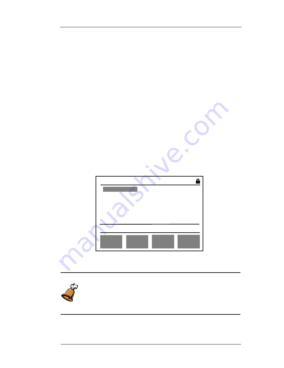
respectively, as shown
in Fig 18a
、
Fig 18b.
Fig 18a: Results menu of
“
Line Parameter
”
(besides ADSL2 and ADSL2+)
Caution:
Pressing
“
AUTO TEST
”
key can auto start the ADSL line parameter test in any
operating menu of the tester, except for
“
DMM
”
testing mode. The displays
will be directly switched into the result menu of
“
Line Parameter
”
and the
“
Start/Stop
”
LED will be turned on.
Result s 00D00H05M03S
[
LINE ANALYS
]
Line st andard G.DMT
Test Channels INT L
Link St ate SUCCESS
LINE
ANALYS
PARAM
ANALYS
ALARM
ANALYS
LINK
ANALYS
i
R u n n i n g . P l e a se v i e w r e s u l t s


