Installation
2–8
975-0330-01-01
Network Layout
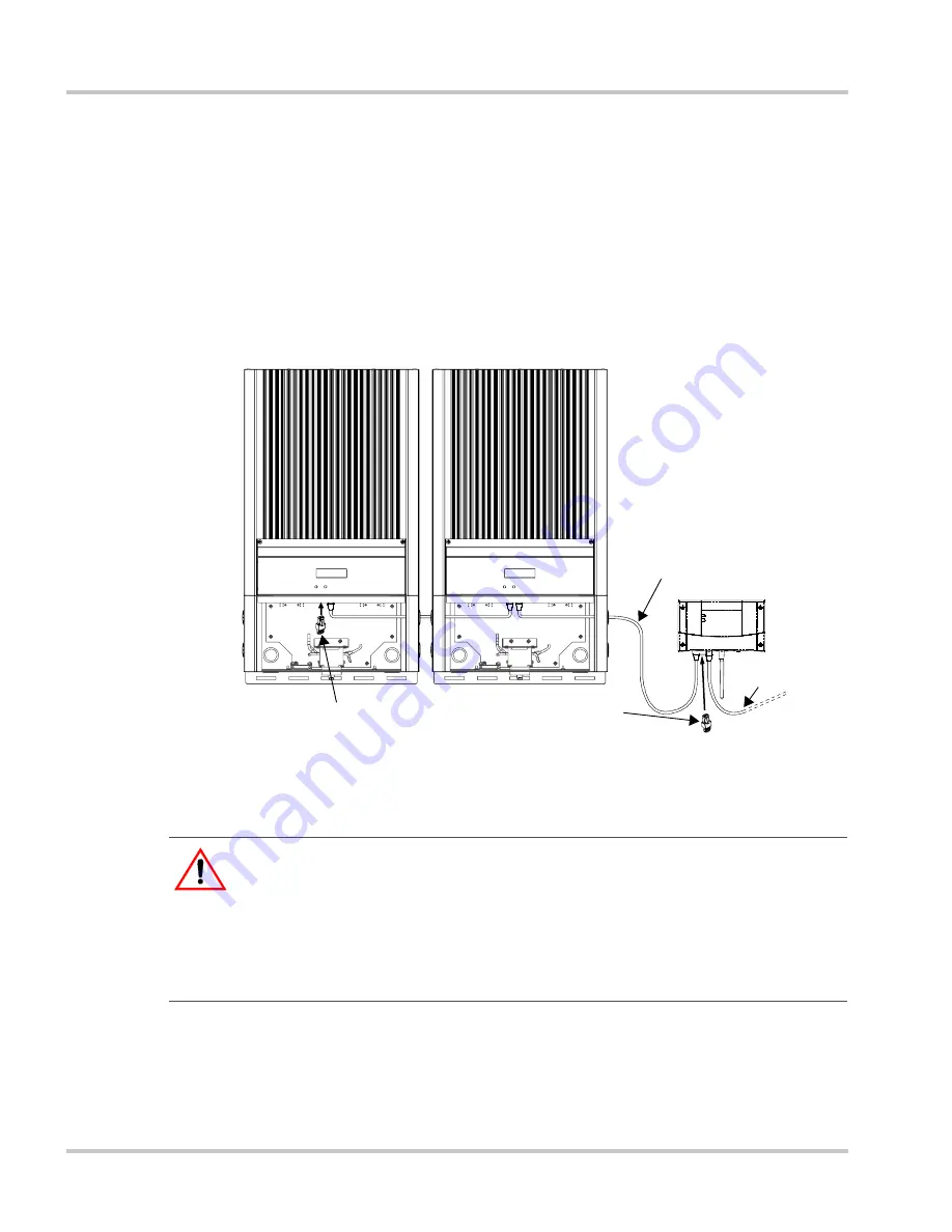
Xanbus-enabled devices are linked with separate lengths of Xanbus cable,
as shown in Figure 2-3.
To ensure communication signal quality, each end of the network must be
terminated. The Xanbus-enabled devices at each end of the network must
have a male terminator inserted into their open network ports.
If the Gateway is the last device on the network, the open Inverter port on
the Gateway must be terminated. See Figure 2-3.
Guidelines for Routing the Network Cables
To ensure maximum performance of your network, follow these
guidelines when routing the network cables.
•
Route the cables away from sharp edges that might damage the
insulation.
Figure 2-3
Network Layout Diagram
:
WARNING: Shock hazard
Do not route the network cables in the same conduit as the AC and DC power
cabling. When connecting and routing the network cable in the inverter wiring
box, make sure the network cable is physically separated from the AC and DC
power cables and any bare live parts by a barrier or by wire routing and securing
means.
Terminator
Terminator
GT Inverters shown with
wiring box covers removed.
Xanbus cable
Ethernet cable
Содержание Communications gateway
Страница 1: ...Communications Gateway Installation Guide Communications Gateway Inverter Modbus RS485 ...
Страница 2: ......
Страница 3: ...Communications Gateway Installation Guide ...
Страница 69: ......


