30
DEU
ENG
NDL
FRA
ITA
ESP
3.2.5 External timer
HZ 5
HZ 6
HZ 7 HZ 8
HZ 9
HZ 10
HZ 11 HZ 12
pump
1 2
boiler
1 2
ECO
1 2
CO
1 2
H %
1 2
HZ 1
HZ 2
HZ 3 HZ 4
1
1
1
1
1
1
2
2
2
2
2
2
1
1
1
1
1
1
2
2
2
2
2
2
1
1
1
1
1
1
2
2
2
2
2
2
N
N
L
L TB
T4AH
N
L
230 V
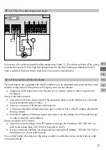
The base station is equipped with an ECO input
for connecting an external timer, if the internal
clock of the room control unit Radio Display
shall not be used. When the input is activated
by the timer, the heating zones are switched to
night operation.
3.2.6 System BUS
HZ 5
HZ 6
HZ 7 HZ 8
HZ 9
HZ 10
HZ 11 HZ 12
pump
1 2
boiler
1 2
ECO
1 2
CO
1 2
H %
1 2
HZ 1
HZ 2
HZ 3 HZ 4
1
1
1
1
1
1
2
2
2
2
2
2
1
1
1
1
1
1
2
2
2
2
2
2
1
1
1
1
1
1
2
2
2
2
2
2
N
N
L
L TB
T4AH
System BUS
B GND
24V A
System BUS
B GND
24V A
System BUS
B GND
24V A
1
7
A maximum of seven base stations can be interconnected via the system BUS (syBUS) in order to
exchange global system parameters. After completing the wiring, the base stations must be paired
– see section 4.2 For a line diameter <6 mm, a strain relief must be provided by the customer.
Note! The base stations can also be connected via radio, see section 4.2. A mix of both variants is
possible.

